


Processor calibration
FlexZone Product Guide
Page 79
Refer to the magnitude response plot created during the locating the cable segment boundaries
tap test procedure to calculate and note the average location of each segment boundary.
Defining sensor cable as non-detecting (setting the start point of detecting cable)
1. Below the Segment Setting window on the Side A Cfig tab, select the Split button.
The Profile graph is divided into 2 sections, the white section is the currently selected
Segment.
2. Use the Range (m) spin control to enter the meter at which detection will begin (the beginning
of the second segment).
3. Use the Segment spin control to select segment 1 (or left-click on the gray portion of the
window).
4. Use the spin controls to assign Segment 1 to Zone 0.
5. Save the UCM file and download the configuration data to the processor.
Defining the detecting cable segments
Once you have defined the lead-in cable section as Zone 0 you can define the detecting cable
according to the site plan. Each time you select the split button, you divide the selected segment
into two equal sections. You then adjust the length of the selected segment and assign the
segment’s zone number for alarm reporting. Each processor can include up to 100 cable
segments (50 per cable side) and up to either 60 (FlexZone-60) or 4 (FlexZone-4) distinct alarm
zones (plus zone 0).
Note
To precisely locate the segment boundaries, you can use the UCM’s
Range (m) spin control to enter the meter where a segment begins. You
can adjust only the start point of each segment using the Range control.
The end of a segment is determined by the beginning of the next
segment, or the end of the detecting cable.
Note
Any sensor cable that is located before the designated start point and
after the designated end point of detecting cable must be set as non-
detecting. Any cable bypasses must also be set as non-detecting.
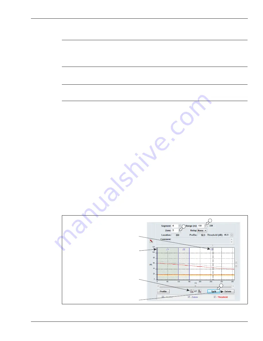
Figure 86: Defining cable segments
1
3
2
magnification buttons
use the Delete button to merge the selected
segment with the preceding segment
no Zone label for segments assigned to Zone 0
the assigned Zone label is centered at the top
of the segment


