background image

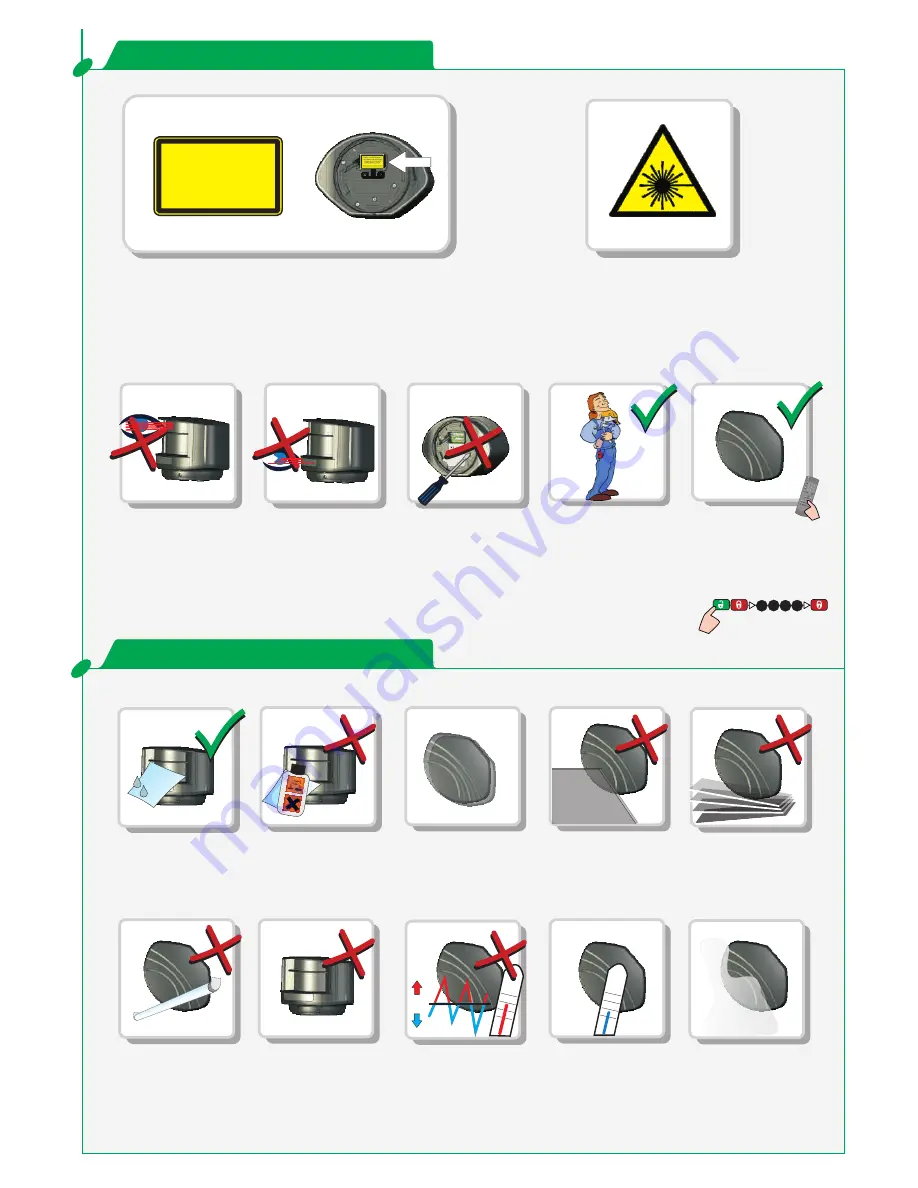
CLASS 1 LASER PRODUCT

CAUTION! CLASS 3R 

LASER RADIATION 

ACCESSIBLE DURING 

INSTALLATION.

1

2

3

4

°C

-0°C

Ex.

F1

F2

?

x2

1

2

3

4

5

6

7

8

0

9

EFA-SCAN

®

=

=

=

=

0°C

°C

2/8

LZR -S600

®

Do not stare into 
the laser emitter.

Do not stare into 
the visible red laser 
beams.

Do not open the 
sensor. Warranty is 
void if opened.

The sensor should 
only be installed 
and adjusted by 
authorized and 
trained staff.

After installation 
enter an access 
code to secure the 
sensor.

Caution! Use of controls, 

adjustments or performance of 

procedures other than those 

specified herein may result in 

hazardous radiation exposure.

The device contains IR and visible red laser diodes.

IR laser (CLASS 1): 

wavelength 905nm
max. output pulse power 75W

Red laser (CLASS 3R): 

wavelength 650nm
max. output CW power 3mW

Fasten the sensor 

firmly to avoid 

vibrations.

If the sensor is used in 

environments where 
the temperature can 

descend below 

0°C, keep the sensor 

permanently powered.

Avoid exposing the 

sensor to sudden and 

extreme temperature 

changes.

Smoke and fog may 

cause unwanted 

detections.

Do not cover 

the front screens.

Avoid moving objects 

in the detection field.

Avoid all types of light 

sources in the 

detection field.

Wipe the front screens  

regularly with a clean 

and damp cloth.

Do not use aggressive 
detergents or abrasive 

cleaning agents to 

clean the front screens.

Avoid condensation.

SAFETY INSTRUCTIONS

INSTALLATION TIPS

2/8

Summary of Contents for LZR -S600

Page 1: ...Cable conduit LED signal Visible laser beams Laser sweep reception Laser sweep emission Tilt angle adjustments Main connector Front screens Caution Exposure to laser radiation Factory values See the...

Page 2: ...e device contains IR and visible red laser diodes IR laser CLASS 1 wavelength 905nm max output pulse power 75W Red laser CLASS 3R wavelength 650nm max output CW power 3mW Fasten the sensor firmly to a...

Page 3: ...sition the sensor correctly The grey area indicates the detection range Position the housing on the bracket Turn the sensor until the two triangles are face to face Position the bracket and fasten the...

Page 4: ...sponding mounting side with background Make sure you stay at a distance to avoid disturbances By choosing a value with background the sensor is protected against misuse The sensor memorizes the refere...

Page 5: ...IONS TEACH IN Field height Field width FIELD 2 FIELD 1 3 sec RED RED RED RED Before teach in you have 3 seconds to step out of the detection field 30 sec TEACH IN Wait for the sensor to learn its envi...

Page 6: ...TMENTS Relay configuration 1 Indoor 2 Outdoor LOW 3 Outdoor MEDIUM 4 Outdoor HIGH 0 size filter deactivated 1 5 cm 2 10 cm 3 15 cm 4 20 cm 1 Active NO 2 Passive NC 3 Passive NC 4 Active NO Passive NC...

Page 7: ...aterial in proximity to the sensor Verify the field size Check the position of the sensor Launch a new teach in Check mounting side setting If there is no background set the mounting side to value 3 t...

Page 8: ...typ 20 ms max 80 ms 2 electronic relays galvanic isolated polarity free 35 V DC 24 V AC 80 mA resistive t 5 ms t 5 ms ON OFF typ 30 0 7 V 20 mA 10 A 1 blue LED power on status 1 orange LED error stat...

Reviews: