SENS IQ Technical Manual
14
Service Hotline: 1.800.742.2326
1.303.678.7500
8 FRONT
PANEL
CONTROLS
8.1
Front Panel User Interface Description
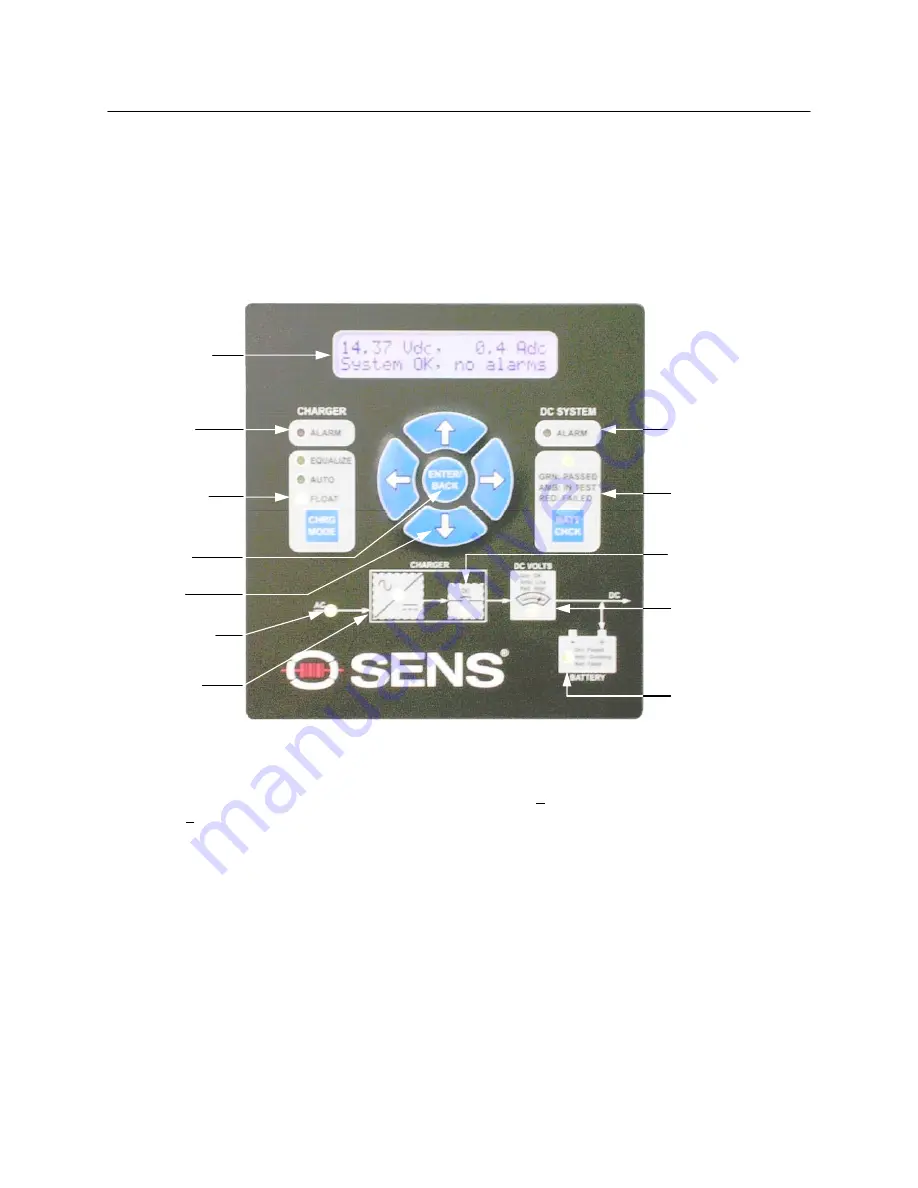
The front panel User Interface provides visual indication of DC output voltage and current, as well as the
charging mode (FLOAT or EQUALIZE), equalize time elapsed, and status of all alarms. The front panel
User Interface is shown below in
FIG 4
.
NOTE:
With no AC mains supply present and with a battery connected to the output of the charger, and with the
DC output breaker closed, the display will operate. Battery voltage and alarm status will be displayed.
With the system in this condition, the charger draws between 200 and 240mA from the battery.
Figure 4: Front Panel User Interface
5. ARROW
BUTTONS
4. ENTER/BACK
BUTTON
2. CHARGER
ALARM LED
1. LCD DISPLAY
3. CHARGE
MODE SELECT
BUTTON AND
STATUS LEDS
6. DC SYSTEM
ALARM LED
7. BATTERY
CHECK BUTTON
AND STATUS
LED
8. AC INPUT LED
9. CHARGER
LED
10. CHARGER
DC BREAKER
LED
11. DC VOLTS
LED
12. BATTERY
LED
1.
LCD DISPLAY
- During normal operation the first line of the LCD
display indicates DC output voltage and current
and the second line indicates alarm status. The display will automatically cycle through alarm status when any
alarms are present. Display will change as User Interface buttons are pressed, to show different menus and config-
uration choices. The output voltage display is accurate to 1%. The Output current display is accurate to
within
+1% or better at room temperature at rated output.
2.
CHARGER ALARM LED
- this is a red master LED indicating any of the following problems:
Over Voltage Shut-
down, DC Breaker Open or Charger Failure alarm (see Section 9.3 for Alarm Definitions). A blank LED indicates
no alarm conditions present.
3.
CHARGE MODE SELECT BUTTON AND STATUS LEDS
- Press CHRG MODE button to switch between
FLOAT, EQUALIZE or AUTO modes (See Section 8.3). The appropriate LED will illuminate to indicate which
mode is active.
4.
ENTER/BACK BUTTON
- Press ENTER/BACK to save a setting or move backward within the
User Interface menus
(see Section 8.6.2 for Menu Options).
5.
ARROW BUTTONS
- Press arrow buttons to move through User Interface menus and increase/decrease configu-
rable values (see Section 8.6.2 for Menu Options).
6.
DC SYSTEM ALARM LED
- this is a red master LED indicating any of the following problems:
Battery Reverse
Polarity, High DC Voltage, Battery Check failed, Battery End-of-Discharge, Low DC Voltage (see Section 9.3 for
Alarm Definitions). Amber indicates a Ground Fault or Battery Discharging alarm. Press the ENTER/BACK key twice
to clear a red LED after a failed Battery Check test. Otherwise, a blank LED indicates no alarm conditions present.


