background image


4.1


INSTALACJA OGRANICZNIKA NAPEŁNIANIA 


WAŻNE: W trakcie montażu zabezpieczyć ogranicznik przed zanieczyszczeniem np. piaskiem ! 

1


Zaleca się zamocować Ogranicznik w osi wzdłużnej zbiornika. 


2


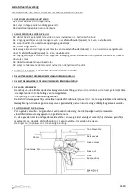
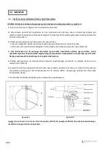
Zamontować  ogranicznik  napełniania  na  tulei  przewodu  pod  pokrywą  włazu,  umieszczając  pływak  pod 

testerem. Należy obowiązkowo zachować odległość co najmniej 50 mm między górą ogranicznika i generatorem 
zbiornika. (Rysunek 2) 


3


Podłączyć przewód (pozycja 2/Rysunek 1) do ogranicznika : 

-


zmierzyć odległość X między pierścieniem włazu (pozycja 1/Rysunek 1) i dnem zbiornika. 

-


skrócić przewód, aby zachować odległość 70 mm między dolną częścią przewodu i dnem zbiornika. 


4


Aby  dostosować  się  do  wymogu  uziemienia  ogranicznika  napełniania  podczas  jego  montażu,  należy 

sprawdzić wyrównanie potencjałów między tuleją przewodu włazu i przewodem w dolnej części ogranicznika. 
Należy przeprowadzić jednostkowy test ciągłości elektrycznej.


5


Założyć pokrywę włazu po zamontowaniu przewodu napełniającego i sprawdzić, czy pływak nie ociera się o 

wewnętrzne przewody. 


6


Sprawdzić  średnicę  odpowietrznika  zbiornika.  Jego  przekrój  powinien  być  równy  co  najmniej  1/4  przekroju 

przewodów napełniających (Art.9 Rozporządzenia z 22 czerwca 1998 r. dotyczącego podziemnych zbiorników 
łatwopalnych cieczy). 


7


Zamontować tabliczkę identyfikacyjną na przewodzie napełniającym. 


Rysunek 1


Rysunek 2


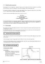
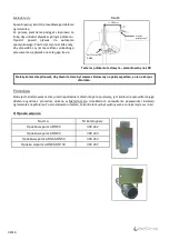
Uwaga: Nie podawać ciśnienia do zbiornika 

poniżej -30 kPa lub powyżej +100 kPa, aby uniknąć ewentualnego 

uszkodzenia w ograniczniku napełniania. 


IV)   

MONTAŻ


50 mm 


Pływak 

Łącznik Nr 2 

Pokrywa zbiornika 
 

Zawór spustowy 
 

POZIOM Nmarks 
 

Obciążniki 

POZIOM N1 

Położenie  
spoczynkowe 
 

Łącznik Nr 1 
 

36/40 

Summary of Contents for DN 100

Page 1: ...A VALLÉECEDEX 1 FRANCE S A S au capital de 315 000 N SIREN 698 202 868 00023 NAF 4674B N TVA FR 25 698 202 868 Tél 33 0 1 60 05 18 53 Fax 33 0 1 60 17 58 39 info selfclimat morvan com www selfclimat morvan com Version 06 2020 Remplace Version 07 2018 Limiteur de remplissage pour hydrocarbures DN 50 DN 80 DN 100 EN 13616 ...

Page 2: ...nérales 3 III Instructions d utilisation 4 3 1 Consignes de sécurité 4 3 2 Mise en service 4 3 3 Fonctionnement 4 IV Montage 6 4 1 Installation du limiteur de remplissage 6 4 2 Entretien et dépannage 7 4 3 Démontage 7 V Conditions particulières 7 VI Accessoires en option 7 VII Données techniques 9 VIII Normes et agréments 10 AVERTISSEMENT MISE EN GARDE FOURNITURES A réception du colis veuillez vou...

Page 3: ...acé sur le tube de remplissage à l intérieur du réservoir de stockage de liquide Cet appareil Dispositif anti débordement à sécurité totale a pour objet de réduire les risques pour l environnement les risques de pollution de l eau ainsi que tout risque d incendie ou d explosion susceptibles de se produire lors du remplissage de réservoirs de stockage de produits industriels ou chimiques Avant son ...

Page 4: ... que les règles générales admises dans le domaine technique doivent impérativement être respectées 3 3 Fonctionnement Introduction Le limiteur de remplissage Self Climat permet le remplissage du réservoir qu il équipe jusqu à un niveau de fermeture N1 A ce niveau il assure une fermeture automatique et complète A ce stade il permet une réouverture pour assurer la vidange du flexible et éventuelleme...

Page 5: ... EST ATTEINT LE LIMITEUR ASSURE UNE FERMETURE TOTALE 4 LE FLOTTEUR EST MAINTENU IMMERGE AU NIVEAU N1 5 PROCEDER À LA FERMETURE DE LA VANNE CAMION ET À LA PRISE D AIR ADDITIONNELLE 6 VIDANGE DU FLEXIBLE Après avoir procédé à la fermeture de la vanne camion et à la prise d air additionnelle l élimination progressive de la pression résiduelle exercée sur le piston est assurée grâce aux trous de fuite...

Page 6: ...issage lors de son montage dans la cuve il convient de s assurer de l équipotentialité entre la douille du tuyau du trou d homme et le tuyau situé en partie basse du limiteur Un test de continuité électrique est à prévoir 5 Remettre le couvercle de trou d homme après montage de la conduite de remplissage et vérifier si le flotteur ne frotte pas contre les tuyaux internes 6 Vérifier le diamètre de ...

Page 7: ...re effectuée par du personnel qualifié 4 3 Démontage Le Limiteur de Remplissage ne peut être démonté qu en cas de dysfonctionnement ou de remplacement de celui ci Il ne peut être démonté que par du personnel habilité à travailler sur du matériel utilisable dans les atmosphères explosibles Les limiteurs de remplissage automatiques Self Climat sont garantis un an contre tout vice de fabrication reco...

Page 8: ...fier son bon fonctionnement avant tout premier remplissage de la cuve selon le procédé décrit dans Méthode de test Ceci permet de valider la bonne installation du LDR Une fois le testeur installé il est obligatoire de procéder à cette vérification au moins une fois par an 2 Collier de support Désignation Référence Collier de support parallèle DN50 avec étrier 308 242 Collier de support parallèle D...

Page 9: ...00 Acier AS 300 Visserie et autres pièces Inox Inox Inox Fonctionnement Type DN 50 Type DN 80 Type DN 100 Raccordement G2 BSP F F G3 BSP F F G4 BSP F F Pression Min 0 15 bar 0 15 bar 0 15 bar Pression Max 6 bar 8 bar 8 bar Débit Min 1 4 m3 h 3 6 m3 h 3 6 m3 h Débit Max 40 m3 h 60 m3 h 84 m3 h Taux de viscosité Max 55 cSt 55 cSt 55 cSt Température 25 C à 60 C 25 C à 60 C 25 C à 60 C Type de dépotag...

Page 10: ... R2016 EN 13616 1 KIWA BRL K636 03 LDR Type DN 100 UL2583 CAN ULC S661 10 R2016 EN 13616 1 KIWA BRL K636 03 Le système Self Climat pouvant fonctionner indépendamment par gravité ou par groupe de pompage son utilisation est aujourd hui préconisée dans la plupart des pays d Europe et du monde entier Siège social Z I Sud Rue des Epinettes CS 50152TORCY 77208 MARNE LA VALLÉECEDEX 1 FRANCE S A S au cap...

Page 11: ...1 FRANCE S A S with capital of 315 000 SIREN registration No 698 202 868 00023 NAF Code 4674B VAT No FR 25 698 202 868 Tel 33 0 1 60 05 18 53 Fax 33 0 1 60 17 58 39 info selfclimat morvan com www selfclimat morvan com Version 06 2020 Remplaces Version 07 2018 Overfill prevention device for liquid petroleum fuels DN 50 DN 80 DN 100 11 40 ...

Page 12: ...RATION OF THE PRODUCT FOR SAFETY REASONS THIS DEVICE SHOULD BE USED BY PERSONNEL AUTHORISED TO WORK ON EQUIPMENT FOR USE IN EXPLOSIVE ATMOSPEHERES PLEASE READ AND DIGEST THIS MANUAL BEFORE USING THE APPLIANCE CONTENTS I Marking 13 II General specifications 13 III Operating instructions 14 3 1 Safety instructions 14 3 2 Starting up 14 3 3 Operation 14 IV Fitting 16 4 1 Installation of the overfill ...

Page 13: ...7 The Self Climat overfill prevention device is a mechanical safety device placed on the filling tube inside the liquid storage tank The purpose of this completely safe overflow prevention device is to reduce environmental risks water pollution risks and all fire or explosion risks that could arise while filling liquid petroleum fuel storage tanks It is essential to verify the compatibility betwee...

Page 14: ...s covering the safety of appliances as well as general rules accepted in technical field must be followed 3 3 Operation Introduction The Self Climat overfill prevention device allows the tank it is fitted to to be filled to a predetermined level L1 At this level it provides automatic and complete closing At this stage it allows reopening for draining the hose and the filler pipe if necessary witho...

Page 15: ...EVEL L1 IS REACHED THE OVERFILL PREVENTION DEVICE IS FULLY CLOSED 4 THE FLOAT IS KEPT SUBMERGED AT THE LEVEL L1 5 CLOSE THE LORRY VALVE AND PROCEED TO THE ADDITIONAL AIR INLET 6 DRAINING THE HOSE After closing the lorry valve and proceeding to the additional air inlet the progressive elimination of the residual pressure on the piston is achieved via the escape holes in the piston chamber casing th...

Page 16: ...f the pipe and the tank bottom 4 To confirm the earthing of the overfill prevention device when fitting it in the tank check that the potentials of the manhole pipe sleeve and the pipe situated at the bottom of the overfill prevention device are the same A test of electric continuity must be carried out 5 Replace the manhole plate after fitting the filler pipe and check that the float cannot rub a...

Page 17: ...out by qualified staff 4 3 Dismantling The overfill prevention device can only be dismantled in the event of malfunctioning or replacement It can only be dismantled by personnel authorized to work on equipment for use in explosive atmospheres Self Climat automatic overfill prevention devices are guaranteed for one year from the invoice date against manufacturing faults accepted by our factory Our ...

Page 18: ...is essential to check its operation according to the procedure described in Test Method before filling the tank for the first time This enables the correct installation of the overfill prevention device to be confirmed Once the tester is installed this check must be performed at least once a year 2 Support clamp Designation Reference Parallel holder clip DN50 308 242 Parallel holder clip DN80 308 ...

Page 19: ...tenings and other parts Stainless steel Stainless steel Stainless steel Operating DN 50 Type DN 80 Type DN 100 Type Connection G2 BSP F F G3 BSP F F G4 BSP F F Min Pressure 0 15 bar 0 15 bar 0 15 bar Max Pressure 6 bar 8 bar 8 bar Min Flow 1 4 m3 h 3 6 m3 h 3 6 m3 h Max Flow 40 m3 h 60 m3 h 84 m3 h Max Viscosity rating 55 cSt 55 cSt 55 cSt Temperature 25 C to 60 C 25 C to 60 C 25 C to 60 C Type of...

Page 20: ...CAN ULC S661 10 R2016 EN 13616 1 KIWA BRL K636 03 DN 100 OPD Type UL2583 CAN ULC S661 10 R2016 EN 13616 1 KIWA BRL K636 03 As the Self Climat system can operate by gravity and with pumps its use is now recommended in most countries in Europe and worldwide Head office Z I Sud Rue des Epinettes CS 50152 TORCY 77208 MARNE LA VALLÉE CEDEX 1 FRANCE S A S with Capital of 315 000 SIREN registration No 69...

Page 21: ...CEDEX 1 FRANCE S A S met een kapitaal van 315 000 Nr SIREN 698 202 868 00023 NAF 4674B Nr BTW FR 25 698 202 868 Tel 33 0 1 60 05 18 53 Fax 33 0 1 60 17 58 39 info selfclimat morvan com www selfclimat morvan com Version 06 2020 Replaces Version 07 2018 Overvulbeveiliging voor vloeibare aardolie producten 21 40 DN 50 DN 80 DN 100 ...

Page 22: ...Gebruiksinstructies 24 3 1 Veiligheidsrichtlijnen 24 3 2 Inbedrijfstelling 24 3 3 Werking 24 IV Installatie 26 4 1 Installatie van de overvulbeveiliging 26 4 2 Onderhoud en reparatie 27 4 3 Demontage 27 V Bijzondere voorwaarden 27 VI Optionele accessoires 27 VII Technische gegevens 29 VIII Normen en goedkeuringen 30 WAARSCHUWING OPGELET BIJ AFLEVERING Controleer bij aflevering of het materiaal in ...

Page 23: ...sche veiligheidsvoorziening die in de inwendige vulleiding van de opslagtank geplaatst wordt Dit toestel Overvulbeveilingssysteem met totale veiligheid moet de risico s voor het milieu de risico s van water verontreiniging en het brand of ontploffingsgevaar beperken die kunnen voorkomen tijdens het vullen van een opslagtank met vloeibare brandstoffen Voor de installatie dient men zich ervan te ver...

Page 24: ...alsmede de algemene regels op technisch gebied moet worden gevolgd 3 3 Werking Inleiding In een reservoir waarin de Self Climat overvulbeveiliging is geïnstalleerd zal gevuld kunnen worden tot het vooraf bepaalde niveau L1 Op dit niveau is zal een automatische sluiting plaatsvinden Na sluiting op niveau L1 gaat de overvulbeveiliging weer open zodat de slang en de eventuele vulleiding kan leegstrom...

Page 25: ...DE OVERVULBEVEILIGING ISVOLLEDIG GESLOTEN 4 DE VLOTTER WORDT ONDERGEDOMPELD GEHOUDEN BIJ NIVEAU L1 5 DE SLUIT DE AFSLUITER OP DE VRACHTWAGEN EN OPENDEBELUCHTING 6 DE SLANG LEEGMAKEN Na sluiting van de afsluiter op de vrachtwagen en beluchting verdwijnt de restdruk op de zuiger geleidelijk door de lekgaten die in de behuizing van de zuigerkamer de opening van de drukontlastingsventiel De kracht die...

Page 26: ...ening na de montage van de overvulbeveiliging in de tank dient men zich te vergewissen dat de er voldoende potentiaalvereffening mogelijk is tussen de leidingaansluiting in het mangat en de leiding onder de overvulbeveiliging Er moet een elektrische continuïteitstest worden uitgevoerd 5 Na montage van de vulleiding het deksel van het mangat terugleggen en controleren of de vlotter vrij kan bewegen...

Page 27: ...e Demontage van de overvulbeveiliging uit de tank is alleen toegestaan bij slechte werking of wanneer deze vervangen moet worden Ze mag alleen gedemonteerd worden door personen die bevoegd zijn om te werken met materiaal dat gebruikt mag worden in omgevingen waar ontploffingsgevaar kan heersen De garantieop door de fabrikant erkende fabricagefouten vaneenSelf Climat overvulbeveiliging is één jaar ...

Page 28: ... de tester geplaatst is moet de correcte werking vóór de eerste vulbeurt van de tank verplicht gecontroleerd worden volgens de werkwijze beschreven in Test methode Dit laat toe de correcte plaatsing van de vulbegrenzer te bevestigen Wanneer de tester geplaatst is moet deze controle minstens één keer per jaar plaatsvinden 2 Steunring Omschrijving Referentie Steunring DN50 parallelle 308 242 Steunri...

Page 29: ...S300 Staal AS300 Schroeven en andere onderdelen Inox Inox Inox Werking DN 50 Type DN 80 Type DN 100 Type Aansluiting G2 BSP F F G3 BSP F F G4 BSP F F Min Druk 0 15 bar 0 15 bar 0 15 bar Max Druk 6 bar 8 bar 8 bar Min Debiet 1 4 m3 h 3 6 m3 h 3 6 m3 h Max Debiet 40 m3 h 60 m3 h 84 m3 h Max Viscositeitsgraad 55 cSt 55 cSt 55 cSt Temperatuur 25 C tot 60 C 25 C tot 60 C 25 C tot 60 C Vullingsmethode P...

Page 30: ... CAN ULC S661 10 R2016 EN 13616 1 KIWA BRL K636 03 Type DN 100 UL2583 CAN ULC S661 10 R2016 EN 13616 1 KIWA BRL K636 03 Het Self Climat systeem is geschikt voor zowel vullen onder vrije val als vullen door middel van een pomp Tegenwoordig wordt het gebruik ervan aanbevolen niet alleen in Europa maar over de hele wereld Hoofdkantoor Z I Sud Rue des Epinettes CS 50152TORCY 77208 MARNE LA VALLÉECEDEX...

Page 31: ...LA VALLÉE CEDEX 1 FRANCJA S A S z kapitalem 315 000 Nr SIREN 698 202 868 00023 NAF 4674B Nr VAT FR 25 698 202 868 Tel 33 0 1 60 05 18 53 Faks 33 0 1 60 17 58 39 info selfclimat morvan com www selfclimat morvan com Version 06 2020 Replaces Version 07 2018 Ogranicznik napełniania do węglowodorów DN 50 DN 80 DN 100 31 40 ...

Page 32: ... SPIS TREŚCI I OZNAKOWANIE 33 II OGÓLNA CHARAKTERYSTYKA 33 III INSTRUKCJE W ZAKRESIE UŻYTKOWANIA 34 3 1 ZASADY BEZPIECZEŃSTWA 34 3 2 URUCHOMIENIE 34 3 3 DZIAŁANIE 34 IV MONTAŻ 36 4 1 INSTALACJA OGRANICZNIKA NAPEŁNIANIA 36 4 2 KONSERWACJA I USUWANIE USTEREK 37 4 3 DEMONTAŻ 37 V SZCZEGÓLNE WARUNKI 37 VI AKCESORIA W OPCJI 37 VII DANE TECHNICZNE 39 VIII NORMY I APROBATY 40 OSTRZEŻENIE UWAGA DOSTAWA Pr...

Page 33: ...st mechanicznym urządzeniem zabezpieczającym mocowanym na rurze napełniającej zbiornika do przechowywania cieczy To w pełni bezpieczne urządzenie zapobiegające przelaniu ma za zadanie ograniczenie zagrożeń dla środowiska ryzyka zanieczyszczenia wody jak również ryzyka pożaru lub wybuchu podczas napełniania zbiorników ciekłego paliwa ropopochodnego Przed instalacją należy bezwzględnie sprawdzić czy...

Page 34: ...także ogólnie przyjętych zasad technicznych 3 3 DZIAŁANIE Wstęp Ogranicznik napełniania Self Climat umożliwia napełnienie zbiornika na którym jest zamontowany do wstępnie ustalonego poziomu N1 po dojściu do tego poziomu ogranicznik zapewnia automatyczne i całkowite zamknięcie Na tym etapie pozwala on na ponowne otwarcie aby umożliwić opróżnienie elastycznego węża ewentualnie przewodów napełniający...

Page 35: ...NICZNIK ZAPEWNIA CAŁKOWITE ZAMKNIĘCIE 4 PŁYWAK POZOSTAJE ZANURZONY NA POZIOMIE N1 5 ZAMKNĄĆ ZAWÓR CIĘŻARÓWKI I ODPOWIETRZYĆ 6 OPRÓŻNIĆ ELASTYCZNY WĄŻ Po zamknięciu zaworu ciężarówki i dodatkowym odpowietrzeniu resztkowe ciśnienie działające na tłok usuwane jest przez otwory przeciekowe nawiercone na osłonie komory tłoka otwór zaworu spustowego Do stopniowej dekompresji dochodzi masa dwóch obciążni...

Page 36: ...as jego montażu należy sprawdzić wyrównanie potencjałów między tuleją przewodu włazu i przewodem w dolnej części ogranicznika Należy przeprowadzić jednostkowy test ciągłości elektrycznej 5 Założyć pokrywę włazu po zamontowaniu przewodu napełniającego i sprawdzić czy pływak nie ociera się o wewnętrzne przewody 6 Sprawdzić średnicę odpowietrznika zbiornika Jego przekrój powinien być równy co najmnie...

Page 37: ...walifikowanych pracowników 4 3 DEMONTAŻ De Ogranicznik napełniania może być zdemontowany wyłącznie w przypadku jego uszkodzenia lub wymiany Demontaż może być przeprowadzony wyłącznie przez pracowników posiadających uprawnienia wymagane do pracy z urządzeniami w strefach zagrożonych wybuchem Automatyczne ograniczniki napełniania Self Climat posiadają roczną gwarancję na wszelkie wady produkcyjne uz...

Page 38: ... tester przed napełnieniem zbiornika po raz pierwszy jest konieczne sprawdzenie jego działania zgodnie z procedurą opisaną w Metoda testu Umożliwia to sprawdzenie poprawności instalacji ogranicznika napełniania Po zainstalowaniu testera ta kontrola musi być wykonywana co najmniej raz w roku 2 Opaska wsporca Nazma Nr katalogowy Opaska wsporcza DN50 308 242 Opaska wsporcza DN80 308 243 Opaska wsporc...

Page 39: ...ty Stal nierdzewna Stal nierdzewna Stal nierdzewna Działanie DN 50 Type DN 80 Type DN 100 Type Podłączenie G2 BSP wewn wewn G3 BSP wewn wewn G4 BSP wewn wewn Ciśnienie min 0 15 bar 0 15 bar 0 15 bar Ciśnienie maks 6 bar 8 bar 8 bar Przepływ min 1 4 m3 h 3 6 m3 h 3 6 m3 h Przepływ maks 40 m3 h 60 m3 h 84 m3 h Lepkość maks 55 cSt 55 cSt 55 cSt Temperatura 25 C do 60 C 25 C do 60 C 25 C do 60 C Sposó...

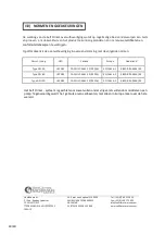
Page 40: ...13616 1 KIWA BRL K636 03 Type DN 100 UL2583 CAN ULC S661 10 R2016 EN 13616 1 KIWA BRL K636 03 Ze względu na to że system Self Climat może działać niezależnie przez spływ grawitacyjny lub za pomocą zespołu pompy jego stosowanie jest zalecane w większości krajów w Europie i na całym świecie Siedziba główna Z I Sud Rue des Epinettes CS 50152 TORCY 77208 MARNE LA VALLÉE CEDEX 1 FRANCJA S A S z kapitał...

Reviews: