Detailed operation
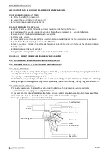
OPERATING PRINCIPLE OF THE SELF CLIMAT STANDARD OVERFILL PREVENTION DEVICES
1)
OVERFILL PREVENTION DEVICE IN THE REST POSITION
-
The float is in the bottom position.
-
The piston is in the top position (fully open).
-
The drain ports are completely open.
2)
THE CLOSING PROCESS BEFORE THE LEVEL L1
-
The float starts to rise progressively under the effect of the hydraulic pressure.
-
The 2 counterweights are moved by spacer No 1 of the float carrier.
-
The piston partially closes the drain ports.
-
The float continues to rise.
-
Half way along the stroke the 2 weights separate from spacer No 1 and are moved by spacer No 2 of the float
carrier.
-
The weights finish rising under the effect of the hydraulic pressure and move the float with them.
-
The drain ports are closed.
-
The piston is in the fully closed position under the effect of hydraulic pressure.
3)
AT THIS POINT THE LEVEL L1 IS REACHED: THE OVERFILL PREVENTION DEVICE IS FULLY CLOSED
4)
THE FLOAT IS KEPT SUBMERGED AT THE LEVEL L1
5)
CLOSE THE LORRY VALVE AND PROCEED TO THE ADDITIONAL AIR INLET
6)
DRAINING THE HOSE
After closing the lorry valve and proceeding to the additional air inlet, the progressive elimination of the
residual pressure on the piston is achieved via:
-
the escape holes in the piston chamber casing.
-
the opening of release valve.
To this progressive decompression, is added the weight of the two counterweights applied to spacer No 2 of
the float carrier which accelerates the partial reopening of the piston and thus allows the hose to drain
completely.
7)
CLOSURE AT LEVEL Lmax
Accidental pouring - excessive hose emptying - failure to observe the flow volumes laid down by the standard
in force. In this case the submerged float continues its stroke, moving the two weights with spacer No 2 of the
float carrier. The piston once again provides complete closure.
50 mm
Top of manhole
Release valve
Level Lmax
Counterweights
Level L1
Rest position
Spacer No 1
Float
Spacer No 2
15/40


