background image

Posizionatore angolare APX 700 - Manuale d'uso - 7


••

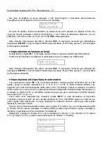
 Alimentazione strumento 


Fornire ai morsetti di alimentazione, come in figura, una tensione di alimentazione di 24, 110 o 220 

Vac 50 Hz. 


caso b - alimentazione: 110Vac

0

110

110Vac

calza

POWER

E

P

COLLEGAMENTI CON LE PRESE DI TERRA

9 10 11 12 13 14 15 16

+

S

C

K

-

S

C

K

-

A

D

T

A

+

D

A

T

A

1 2 3 4 5 6 7 8

+

-

L

I

M

E

N

C

C

O

M

+

-

POWER

P

/

N

M0

M1

M2

M3

presa di Terra

caso a - alimentazione: 24Vac

0

24

E

P

24Vac

calza

POWER

caso c - alimentazione: 220Vac

0

220

220Vac

calza

POWER

E

P


Summary of Contents for APX 7 Series

Page 1: ...SELET SENSOR APX700 1 2 3 4 5 6 7 8 9 101 1 1 2 13 1 4 15 1 6 POWER LIM ENC ESC 0 FN 7 8 9 4 5 6 1 2 3 OFF ON X SERIE Posizionatori angolari Encoder programmers APX 7 ...

Page 2: ...po lineare automatico 17 Visualizzazione delle impostazioni correnti 20 Programmazione 21 Spostamento all impulso precedente successivo 22 Spostamento alla camma precedente successiva 22 Spostamento avanti indietro a pagine 22 Spostamento avanti indietro di 4 camme 22 Attivazione Disattivazione dell impulso corrente 22 Inversione dello stato dell impulso corrente 23 Spostamento al grado X 23 Cambi...

Page 3: ...delay notation 42 Setting automatic linear advance 42 Looking at current configuration 45 Programming 46 Moving to previous next state 47 Moving to previous next output 47 Moving forward backward by pages 47 Moving 4 outputs forward backward 47 Setting Resetting current state 47 Inverting NOT current state 48 Moving to a specified degree 48 Changing programming mode cycle 48 Programming a block of...

Page 4: ...l impulso corrente FN 0 Spostamento al grado X FN 1 Cambia modo ciclo di programmazione FN 2 Programmazione di un blocco di impulsi FN 3 Test delle programmazioni del modo corrente FN 4 Azzeramento delle programmazioni di una camma FN 5 Azzeramento totale della memoria FN 6 Duplicazione di una camma FN 8 Associazione della camma corrente all anticipo FN 9 Visualizzazione delle impostazioni corrent...

Page 5: ...re 220 Vac da specificare 8 V Relè mancata presenza encoder o errore NC 9 V Relè velocità limite raggiunta NC 10 Ingressi encoder Gray 11 V Ingressi selezione modo binario 0000 1111 è 0 15 12 V Morsetti per rete locale con LP Selet Sensor solo opzione N 13 Porta seriale RS 232c 485 colloquio PC solo opzione N 14 V Uscite statiche optoisolate 15 Prese di Terra V lo strumento viene fornito con morse...

Page 6: ...te su appositi LED Visualizzazione della posizione angolare dell encoder in fase di test del programma Visualizzazione della velocità in RPM giri min dell encoder in fase di esecuzione Impostazione di una velocità limite in RPM giri min Impostazione dello zero relativo dell encoder e del senso di rotazione positiva Possibilità di impostare l anticipo lineare automatico per bancate 1 4 5 8 9 12 13 ...

Page 7: ...ite statiche optoisolate 16 PNP o NPN 35 V 100 mA RPM visualizzazione reale della velocità dell encoder giri min Sfasamenti 4 diversi anticipi lineari automatici uno per ogni gruppo di 4 camme fino a 300 ms oppure 99 tra 100 e 3000 RPM Memoria I dati sono mantenuti nel tempo per una durata di 10 anni circa anche in assenza di alimenta zione tecnologia E PROM Sono possibili circa 10000 riscritture ...

Page 8: ...e di 24 110 o 220 Vac 50 Hz caso b alimentazione 110Vac 0 110 110Vac calza POWER E P COLLEGAMENTI CON LE PRESE DI TERRA 9 10 11 12 13 14 15 16 S C K S C K A D T A D A T A 1 2 3 4 5 6 7 8 L I M E N C C O M POWER P N M0 M1 M2 M3 presa di Terra caso a alimentazione 24Vac 0 24 E P 24Vac calza POWER caso c alimentazione 220Vac 0 220 220Vac calza POWER E P ...

Page 9: ...denza dei morsetti del connettore DB15 secondo quanto riportato di seguito Bit 7 Bit 6 Bit 5 Bit 4 Bit 3 Bit 2 Bit 1 Bit 0 n c P N COM M3 Bit 8 Bit 9 solo per encoder da 720 i g PIN OUT DEL CONNETTORE DB15 E POSIZIONE DEI PONTICELLI PER IL COLLEGAMENTO CON ENCODER PNP 1 8 9 15 Se si utilizzano encoder tipo SAO 63 i collegamenti del cavo con il connettore e con l APX 700 si riferiscono alla seguent...

Page 10: ...selezionare attraverso la funzione FN 5 modalità di selezione modo ciclo attivo l opzione 1 ESTERNA Quindi collegare i morsetti d ingresso M0 M3 come mostrato di seguito P N M0 M1 M2 M3 DB15 Riportiamo di seguito la tabella delle combinazioni dei morsetti M0 M3 che permettono di determinare il numero di modi complessivi M3 M2 M1 M0 Modo attivo 0 0 0 0 0 0 0 0 1 1 0 0 1 0 2 0 0 1 1 3 0 1 0 0 4 0 1 ...

Page 11: ...ione PNP APX 700 OUT n Rele Uscite Alimentazione NPN APX 700 Collegamento in rete Lo strumento APX 700 N è predisposto per funzionare come terminale SLAVE in una rete locale sincrona SPI comprendente le logiche programmabili della Selet Sensor il modulo MASTER ha la facoltà di interrogare l APX 700 N ottenendo informazioni sullo stato delle camme sulla posizione assoluta e relativa dell encoder e ...

Page 12: ...Rete disabilitata collegamento P C APX700 Riservato Indirizzo 1 31 0 non valido Nella figura precedente l indirizzo selezionato è 00110 6 Se la rete è disabilitata selettore 8 a 0 l APX 700 N non potrà essere interrogato anche se collegato correttamente Il selettore n 7 permette di selezionare il tipo di collegamento standard punto punto P C APX700 mediante il connettore DB9 Stato Collegamento Dis...

Page 13: ... Zero relativo Zero assoluto encoder Selezione modo manuale in programmazione Ripristino di errore automatico Encoder PNP Anticipi espressi in gradi Nessun anticipo impostato Lingua italiana Vengono qui di seguito descritte le varie procedure di configurazione Modalità Tasto Effetto Configurazione FN 0 Modifica codice abilitazione tastiera FN 1 Impostazione numero camme FN 2 Impostazioni encoder t...

Page 14: ...mme Con quest opzione è possibile impostare il numero di uscite camme programmabili da APX 700 questo valore influisce anche sul numero di modi cicli di programmazione disponibili come da tabella sottostante Uscite camme Modi cicli 8 16 16 8 Premere FN 1 per attivare quest opzione Se è stato introdotto un valore valido verrà richiesta la conferma premere ENTER 8 per confermare l impostazione oppur...

Page 15: ... antiorario se ne leggeranno 120 Se il valore introdotto è corretto 0 o 1 verrà richiesta la conferma premere ENTER per confermare l impostazione oppure ESC per abbandonare Nota Durante l introduzione del valore premere ESC in qualunque momento per abbandonare l operazione ENTER per terminare l introduzione del valore di una cifra oppure premere per cancellare la cifra appena introdotta Velocità l...

Page 16: ...possibile selezionare il modo attivo in programmazione il modo attivo è il modo corrente oppure tramite i 4 ingressi esterni alimentazione 12 Vcc offrendo quindi la possibilità di selezione interattiva del modo ad esempio con un contraves o tramite una logica programmabile ecc Selezionando la selezione manuale il modo attivo in esecuzione è il modo impostato in programmazione e l unico modo di cam...

Page 17: ...ico Con quest opzione tasto FN 8 è possibile impostare l anticipo lineare automatico per uno dei quattro gruppi di camme disponibili 1 4 5 8 9 12 e 13 16 È infatti possibile stabilire che raggiunta una certa velocità angolare dell encoder APX 700 anticipi o ritardi le variazioni di livello di alcune camme di un certo numero di gradi proporzionale lineare alla velocità corrente ad esempio se si imp...

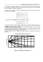
Page 18: ... velocità a cui deve intervenire il valore di anticipo o ritardo per cui basta introdurre tale valore ed infine confermare con ENTER oppure abbandonare con ESC Il grafico seguente evidenzia alcune rette di anticipo e ritardo lineare espresso in gradi seguendo una particolare retta si potrà osservare il relativo sfasamento ad una velocità compresa tra 0 e 3000 RPM per comodità non sono state riport...

Page 19: ...i della velocità compresi tra 0 ed il valore impostato da tastiera e viene gestito automaticamente dallo strumento N valore impostato da tastiera X numero di gradi di sfasamento impostati da tastiera da ottenere ad N RPM Il valore corretto da impostare è RPM 12 700 si è considerato il valore assoluto di X poiché si è già specificato precedentemente se si trattava di anticipo o di ritardo Ad esempi...

Page 20: ...ncellare la cifra appena introdotta E da tenere presente che la minima lunghezza dell impulso di programmazione espressa in gradi è funzione della velocità di rotazione reale dell encoder Analizzando il grafico riportato nella pagina seguente il quale è calcolato nelle condizioni peggiori 16 uscite impostate e 4 anticipi attivi si comprende ad esempio che per un impulso lungo 2 gradi la massima ve...

Page 21: ...e Modalità Tasto Effetto Programmazione Spostamento all impulso precedente successivo Spostamento alla camma precedente successiva FN Spostamento avanti indietro a pagine FN Spostamento avanti indietro di 4 camme ON Attivazione dell impulso corrente OFF Disattivazione dell impulso corrente ENTER Inversione dello stato dell impulso corrente FN 0 Spostamento al grado X FN 1 Cambia modo ciclo di prog...

Page 22: ...tasti FN è possibile spostarsi per pagine lungo il treno d impulsi della programmazione della camma correntemente visualizzata ogni pagina contiene il numero di impulsi contemporaneamente visualizzabili sul display LCD cioè 13 Spostamento avanti indietro di 4 camme Per spostarsi più velocemente sulle camme programmabili è sufficiente premere i tasti FN la visualizzazione si sposterà di 4 camme ava...

Page 23: ...7 memorizzata NO per il ciclo 0 può essere memorizzata NC per il ciclo 1 e così via Quindi in funzione del ciclo macchina dopo aver effettuato la programmazione una sola volta possiamo far lavorare l uscita 7 NO oppure NC cambiando unicamente il ciclo di programmazione attivo attraverso quest opzione la quale è valida per tutte le uscite Una volta cambiato il ciclo di programmazione questa imposta...

Page 24: ...ione del cursore è possibile ricorrere a quest opzione FN 3 la quale permette di osservare lo stato delle uscite le quali rimangono OFF ma vengono attivati solo i LED in base alla posizione dell encoder è quindi possibile far ruotare l encoder scollegato dalla macchina ed osservare il comportamento delle uscite Come si può osservare in figura viene visualizzata la posizione corrente dell encoder e...

Page 25: ...care un singolo modo verrà richiesto il modo da duplicare In entrambi i casi alla fine verrà richiesta conferma per l operazione di duplicazione premere ENTER per confermare o ESC per abbandonare Nota Durante l introduzione dei valori premere ESC in qualunque momento per abbandonare l operazione ENTER per terminare l introduzione del valore oppure per cancellare la cifra appena introdotta Associaz...

Page 26: ...re 0 ms l eventuale V non sarà visualizzato e quest opzione non sarà disponibile Visualizzazione delle impostazioni correnti Con quest opzione FN 9 è possibile osservare tutte le impostazioni correnti numero di uscite velocità limite posizione dello zero anticipi ecc Viene visualizzata una serie di schermate informative dalla quale è possibile uscire in ogni momento premendo ESC premendo invece un...

Page 27: ...ite vengono spente e viene attivato il menu di Configurazione Programmazione IMPORTANTE esiste un codice di riserva sempre valido nel caso in cui vi dimenticaste il codice di accesso da voi impostato Tale codice è 371372 Protezione delle uscite contro i cortocircuiti APX700 è dotato di una nuova ed efficace funzione per la protezione automatica delle uscite contro eventuali cortocircuiti Infatti a...

Page 28: ...etto PE dell alimentazione vedere paragrafo Alimentazione strumento Si consiglia di alimentare lo strumento separatamente da sensori attuatori e Personal Computer verificare il corretto cablaggio e l innesto sicuro di connettori o cavi nelle morsettiere prima di fornire l alimentazione allo strumento ƒ munire i dispositivi di potenza es inverter motori ecc di appositi filtri di rete ed opportune s...

Page 29: ...current state FN 0 Go to degree state X FN 1 Change current programming mode cycle FN 2 Program a block of states FN 3 Test current programming mode cycle FN 4 Clear an output program FN 5 Clear whole program FN 6 Duplicate an output program FN 8 Join current output to the advance FN 9 Display current configuration ESC Switch to Configuration Programming mode Configuration Programming FN ON Activa...

Page 30: ...r supply to specify 8 V Encoder error relay NC 9 V Speed limit reached relay NC 10 Encoder input Gray code 11 V Mode selction inputs binary 0000 1111 Á 0 15 12 V Selet Sensor s PL LAN connector N option only 13 Serial port RS232c 485 for PC connection N option only 14 V Static outputs 15 Earth terminals V the instrument includes the extractable connectors General features The encoder programmer AP...

Page 31: ... LEDs Displaying of encoder position angle during outputs test Displaying of the real speed in RPM rounds per minute during execution Possibility to set a speed limit in RPM rounds per minute Possibility to set direction and relative zero of the encoder Automatic linear advance set for each 4 cams 1 4 5 8 9 12 13 16 and relative cam advance association up to 99 between 100 and 3000 rpm or until 30...

Page 32: ...ls SCK SCK DATA DATA Static and opto insulated 16 PNP or NPN 35 V 100 mA RPM Displaying real encoder speed round for minute Advance 4 different linear advances one for each 4 cams group until 300 ms or up to 99 between 100 and 3000 RPM Memory Data are mainteined for about 10 years even Without any power supply EEPROM technology There are about 10000 writing available for any Memory cell before EEP...

Page 33: ...r 220 Vac 50 Hz EARTH TERMINALS CONNECTIONS 9 10 11 12 13 14 15 16 S C K S C K A D T A D A T A 1 2 3 4 5 6 7 8 L I M E N C C O M POWER P N M0 M1 M2 M3 Earth terminal case a power supply 24Vac 0 24 E P 24Vac braiding POWER case c power supply 220Vac 0 220 220Vac braiding POWER E P case b power supply 110Vac 0 110 110Vac braiding POWER E P ...

Page 34: ...responding to the pins of the DB 15 connector Bit 7 Bit 6 Bit 5 Bit 4 Bit 3 Bit 2 Bit 1 Bit 0 n c P N COM M3 Bit 8 Bit 9 only for 720 i r encoder DB15 CONNECTOR PIN OUT AND POSITION OF THE JUMPERS FOR PNP ENCODER CONNECTION 1 8 9 15 If you are using SAO 63 encoder the connection between encoder and APX 700 refers to the following table Definition Connector Wire color 12 Volts V Brown 0 Volts T Blu...

Page 35: ...ough the function FN 5 setting mode cycle selection type the option 1 EXTERNAL Then connect the input terminals M0 M3 in according to the encoder type used PNP or NPN like shown below P N M0 M1 M2 M3 DB15 We report the combinations table of the M0 M3 terminals that permitts to define the overall number of modes M3 M2 M1 M0 Active mode 0 0 0 0 0 0 0 0 1 1 0 0 1 0 2 0 0 1 1 3 0 1 0 0 4 0 1 0 1 5 0 1...

Page 36: ...table to place a diode in parallel with the coil OUT n Relay Supply Output Power PNP APX 700 OUT n Relay Supply Output Power NPN APX 700 Network connection APX 700 N is capable of working as SLAVE terminal in a synchronous LAN SPI including Selet Sensor s PLs the MASTER PL can query APX 700 N getting information about cams state absolute and relative encoder position and encoder speed For more inf...

Page 37: ...erved Address 1 31 0 illegal In the figure above the address set is 00110 6 If the network connection is disabled 8th selector 0 APX 700 N will not be able to respond to master queries even if correctly connected Switch 7 permits to select the type of standard point to point connection between P C and APX700 through the DB 9 connector State Connection Max distance 1 ON P C RS 485 2 Km at 38 8 Kbit...

Page 38: ...wise Relative zero Absolute zero Manual mode selection in programming Automatic error recovering PNP encoder Advance delay notation degree No advance set English language In the rest of the chapter we will describe each configuration option Modalità Tasto Effetto Configurazione FN 0 Change keyboard access code FN 1 Set number of outputs FN 2 Encoder setup type PNP NPN positive direction speed limi...

Page 39: ...bort the operation ENTER to end code MAX 6 digits Setting number of outputs Using this option you can set the number of programmable outputs cams this value also affect the number of available programming modes cycles as in table below Outputs cams Modes cycles 8 16 16 8 Press FN 1 to select this option If you have entered a correct value APX 700 asks for a confirm press ENTER to confirm operation...

Page 40: ...ockwise or anticlockwise e g if APX 700 reads 240 with clockwise direction it will read 120 when direction is anticlockwise If you have entered a correct value 0 or 1 APX 700 asks for a confirm press ENTER to confirm setting or ESC to abort Speed limit While executing current program APX 700 displays the real speed of the encoder in RPM rounds per minute if the speed exceeds the limit set the LIM ...

Page 41: ...cle active while APX 700 is running as mentioned in the paragraph relative to general features it s possibile to select the active mode during programming the active mode is the current one or rather by the 4 external inputs 12 Vcc power supply offering an interactive selection of the active mode e g by contraves or Programmable Logic etc Using manual selection the active mode while running is the...

Page 42: ... a single digit or to delete the last digit entered Setting automatic linear advance Using this option key FN 8 you can set the automatic linear advance for one of the four output groups available 1 4 5 8 9 12 and 13 16 In fact it s possible to program APX 700 to advance or delay the states flow of some cams according to the current angular speed of the encoder linearly for example if you set an a...

Page 43: ...t operate the advance delay value therefore is enough insert this value and in the end confirm with ENTER or abort with ESC The graph below shows some advance and delay lines looking at a particular line you can see the phase displacement for speeds lower than 3000 RPM speeds greater than 3000 RPM are not reported but are possible Advance delay diagram degrees rpm R P M ADVANCE DELAY DEGREES 110 9...

Page 44: ...ebrical expression Value RPM X N where RPM represents the range of values of speed included between 0 and the value setting by keyboard and it is manage automatically by instrument N value setting by keyboard X number of degrees of advance delay setting by keyboard to get at N RPM The right value to set is RPM 12 700 where the absolute value of X is intended because you have already specified befo...

Page 45: ... current value or to delete the last digit entered The least lenght of programming impulse express with degrees is a function of real rotation speed of the encoder Analyzing the graph of the next page which is calculate in the worse conditions 16 out selected and 4 active advances delays is possible to understand for example that for an impulse of 2 the maximum rotation speed is 900 RPM Minimum le...

Page 46: ...e chapter we will describe each programming option Mode Key Effect Programming Move to previous next state Move to previous next output FN Move forward backward by pages FN Move 4 outputs forward backward ON Set current state OFF Reset current state ENTER Invert NOT current state FN 0 Go to degree state X FN 1 Change current programming mode cycle FN 2 Program a block of states FN 3 Test current p...

Page 47: ...ward backward by pages Similarly to moving one impulse at a time by pressing keys FN you can move through the train of impulses of the current output but a page at a time that is 13 degrees Moving 4 outputs forward backward To move faster through the outputs it s sufficient to press keys FN APX 700 will move 4 outputs forward backward if possible Setting Resetting current state As already mentione...

Page 48: ...different cycles that means e g that output 7 programmed NO for cycle 0 can be programmed NC for cycle 1 and so on Thus according to the cycle of the machine the output 7 can work as NO or NC contact but you have programmed it only a time simply changing current mode Tis is valid for each output Once you have changed the programming cycle this setting is valid either in programming or in execution...

Page 49: ...cording to the position of the encoder thus it s possible to turn the encoder for example manually and look at the outputs behaviour As you can see in the figure the current position of the encoder is displayed and the test proceeds until you press ESC Clearing an output program Using this option you can clear the program of a single output relatively to a single mode cycle or to all mode availabl...

Page 50: ...PX700 and we said that there is an advance for each group of 4 cams 1 4 5 8 9 12 13 16 but we never mentioned how to hook a cam to the advance It s sufficient to press FN 8 and immediately the current cam will be associated to the advance currently set for that group By pressing FN 8 again the cam will be released from the advance At any time you can see if a cam is advanced or not by looking at i...

Page 51: ...always valid as backdoor if you forget your own access code This code is 371372 Outputs protection against short circuit APX 700 is equipped with a new and useful function relative to the automatic protection of the outputs against possible short circuits In fact when an output short circuit is checked e g the number 15 the instrument switches in high impedance mode So it divides the outputs from ...

Page 52: ...onnected for this purpose we recommend to use the PE terminal of the power supply see the paragraph APX 700 supply voltage We recommend to supply the instrument separately from sensors actuators and Personal Computer before provide the instrument power supply verify the right wiring harness and the safe coupling of connectors into the terminals ƒ to provide the opportune screening cables and prope...

Page 53: ...Settembre September 2002 Selet Sensor s r l Via Pozzo 16 10151 Torino ITALY Tel 39 011 4537811 Fax 39 011 4537868 E mail info selet it http selet it FILE NAME man_apx7 pdf ...

Reviews: