48
ATSEL HMI User Manual
2. Project design
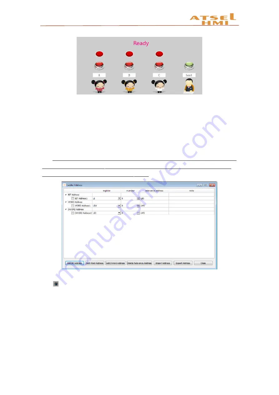
A. Establish corresponding table of the address. Establish the address separately,
and relevant the ladder diagram address according to the actual address. The project
contains 7 switch addresses (4 inputs, 3 outputs) and 1 multi-state display (word
address). Add notices of the address name.
Remarks: The address of the ladder diagram can be numbered
arbitrary not relevant
with bit, word or double word
. Register LI and LQ
no need to attention
actual input and
output. For example, V0.0 can be
relevant
LQ10.
B. Ladder diagram Programming is based on ladder address. During programming,
click to display the relevant address for easy writing.


