background image


User Manual – SEFRAM 53X2DC 

47 

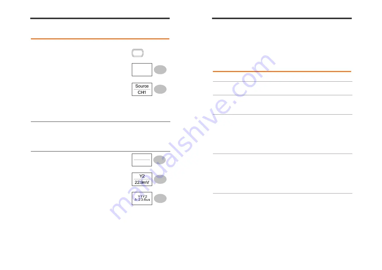
Using the vertical cursors 


Procedure 

1.


Press the Cursor key. 

Cursor


2.


Press 

X

Y

 to select the 

vertical (Y1&Y2) cursor. 

X

Y


3.


Press 

Source

 repeatedly to 

select the source channel. 


 Range 

CH1, 2, Math 


4.


The cursor measurement results will appear in 
the menu. 

Parameters Y1 

Voltage level of the upper cursor 

 Y2 

Voltage level of the lower cursor 


The voltage difference between the upper 
and lower cursor 

Moving the 
vertical cursors 

To move the upper cursor, 
press 

Y1

 and then use the 

Variable knob. 

Y1

123.4mV


To move the lower cursor, 
press 

Y2

 and then use the 

Variable knob. 


To move both cursors at once, 
press 

Y1Y2

 and then use the 

Variable knob. 


User Manual – SEFRAM 53X2DC 

48


Math Operations 

The Math operations can add, subtract, or perform FFT on the input 
waveforms. The resulted waveform can be measured using the 
cursors, and saved or recalled just like normal input signals. 

Overview 


Addition (+) 

Adds amplitude of CH1 & CH2 signals. 

Subtraction (–) 

Extracts the amplitude difference between CH1 & 
CH2. 

FFT 

Runs FFT calculation on a signal. Four types of 
FFT windows are available: Hanning, Flattop, 
Rectangular, and Blackman. 

Frequency 

resolution 

Good 

Hanning FFT 

window 

Amplitude 

resolution 

Not good 

 Suitable 

for.... 

Frequency measurement on 
periodic waveforms 

Frequency 
resolution 

Not good 

Flattop FFT 
window 

Amplitude 

resolution 

Good 

 Suitable 

for.... 

Amplitude measurement on 
periodic waveforms 

Frequency 

resolution 

Very good 

Rectangular FFT 

window 

Amplitude 

resolution 

Bad 

 Suitable 

for.... 

Single-shot phenomenon 
(this mode is the same as 
having no window at all) 

Summary of Contents for 5322DC

Page 1: ...Digital Storage Oscilloscope SEFRAM 5322DC 5342DC 5362DC 5382DC USER MANUAL M53X2DC A 00...

Page 2: ...ty key 1 4 32 Utility key 2 4 33 Utility key 3 4 33 Utility key 4 4 33 Default Settings 34 Built in Help 35 MEASUREMENT 36 Basic Measurements 36 Activating a channel 36 Using the Autoset 37 Running an...

Page 3: ...aving the panel settings 83 Saving the waveform 84 Saving the display image 85 Saving all panel settings display image waveform 86 Recall 88 File type source destination 88 Recalling the default panel...

Page 4: ...the ground side of the BNC connectors It might lead to fire and electric shock Do not place heavy objects on the oscilloscope Avoid severe impacts or rough handling that may damage the oscilloscope A...

Page 5: ...e below Relative Humidity 80 Altitude 2000m Temperature 0 C to 50 C User Manual SEFRAM 53X2DC 10 Pollution Degree EN 61010 1 2001 specifies the pollution degrees and their requirements as follows the...

Page 6: ...Subtract FFT Edge video pulse width trigger Compact size W 310 x D 140 x H 142 mm Interface SD card connector for saving and recalling data Calibration output External trigger input SD card slave con...

Page 7: ...e single trigger mode page72 Trigger force key FORCE Acquires the input signal once regardless of the trigger condition at the time page72 Horizontal menu key MENU Configures the horizontal view page5...

Page 8: ...orizontal status Frequency Trigger condition Waveform position Trigger status Acquisition Menu Waveforms Channel 1 Yellow Channel 2 Blue Trigger status Trig d A signal is being triggered Trig Waiting...

Page 9: ...cord 2 Press the power switch The display will become active in approximately 10 seconds 3 Reset the system by recalling the factory settings Press the Save Recall key then Default Setup For details o...

Page 10: ...age52 User Manual SEFRAM 53X2DC 20 QUICK REFERENCE This chapter lists the oscilloscope menu tree operation shortcuts built in help coverage and default factory settings Use this chapter as a handy ref...

Page 11: ...BW Limit Off Probe x1 CH 1 Probe Cursor key 1 2 Turn cursor on off Cursor Move X1 cursor X1 VAR Move X2 cursor X2 VAR Move both X1 and X2 cursor X1X2 VAR Switch to Y cursor X Y User Manual SEFRAM 53X2...

Page 12: ...w roll mode Roll Select XY mode XY User Manual SEFRAM 53X2DC 24 Math key 1 2 Math on off Math Select math operation type Operation Select addition subtraction CH1 CH2 Set result position Position VAR...

Page 13: ...ze waveform or trigger Run Stop User Manual SEFRAM 53X2DC 26 Save Recall key 1 9 Switch to Save or Recall menu Save Recall Recall default setup Default Setup Save Recall key 2 9 Select other menu Reca...

Page 14: ...ef waveform B on off Ref B User Manual SEFRAM 53X2DC 28 Save Recall key 5 9 Select other menu Save Setup Select destination Destination VAR Save setup Save Go to SD card file utilities File Utilities...

Page 15: ...l Save Go to SD card file utilities File Utilities User Manual SEFRAM 53X2DC 30 Save Recall key 9 9 Select file folder VAR Select Create or rename folder file New Folder Rename VAR Enter character Bac...

Page 16: ...ource Source Select pulse trigger condition and pulse width When VAR Go to slope coupling menu page32 Slope Coupling Select trigger mode Mode User Manual SEFRAM 53X2DC 32 Trigger key 4 4 Select trigge...

Page 17: ...revious Menu User Manual SEFRAM 53X2DC 34 Default Settings Here are the factory installed panel settings which appear when pressing the Save Recall key Default Setup Acquisition Mode Normal Channel Sc...

Page 18: ...o exit the Help mode Help User Manual SEFRAM 53X2DC 36 MEASUREMENT The Measurement chapter describes how to properly observe a signal using the oscilloscope s basic functionalities and how to observed...

Page 19: ...tion Before Autoset After Autoset Undoing the Autoset To undo the Autoset press Undo available for 5 seconds Adjusting the trigger level If the waveform is still unstable try adjusting the trigger lev...

Page 20: ...ect the timebase scale turn the TIME DIV knob left slow or right fast TIME DIV Selecting the horizontal scale Range 1ns Div 10s Div 1 2 5 increment Changing the vertical position and scale For more de...

Page 21: ...1 Connect the probe between the compensation signal output and Channel input View the probe compensation waveform VOLTS DIV VOLTS DIV TIME DIV CH 1 MATH CH 2 MENU MENU Acquire Display Utility Help Run...

Page 22: ...ive peak voltage Vamp Difference between global high and global low voltage Vhi Vlo Vhi Global high voltage Vlo Global low voltage User Manual SEFRAM 53X2DC 44 Vavg Averaged voltage of the first cycle...

Page 23: ...ws the precise position of the input waveforms or math operation result Using the horizontal cursors Procedure 1 Press the Cursor key The cursors appear in the display Cursor 2 Press X Y to select the...

Page 24: ...FRAM 53X2DC 48 Math Operations The Math operations can add subtract or perform FFT on the input waveforms The resulted waveform can be measured using the cursors and saved or recalled just like normal...

Page 25: ...C 50 Adding or subtracting signals Procedure 1 Activate both CH1 and CH2 CH 1 CH 2 2 Press the Math key MATH 3 Press Operation repeatedly to select addition or subtraction 4 The math measurement resul...

Page 26: ...ical scale of FFT waveform press Unit Div repeatedly Range 1 2 5 10 20 dB Div 8 To clear the FFT result from the display press the Math key again MATH User Manual SEFRAM 53X2DC 52 CONFIGURATION The Co...

Page 27: ...center of the display Autoset 6 Press the Acquire key Acquire User Manual SEFRAM 53X2DC 54 7 Press Normal 8 Press Peak Detect and see that a spike noise is captured Peak Detect On Example The peak det...

Page 28: ...useful for observing waveform variation 1 Press the Display key Display Procedure 2 Press Accumulate to turn on the waveform accumulation Accumulate On 3 To clear the accumulation and start it over re...

Page 29: ...e waveform update mode Background The display update mode is switched automatically or manually according to the horizontal scale Main mode Updates the whole displayed waveform at once The main mode i...

Page 30: ...waveforms in the X Y mode Background The X Y mode compares the voltage of Channel 1 and Channel 2 waveforms in a single display This mode is useful for observing the phase relationship between the two...

Page 31: ...ing the vertical scale Procedure To change the vertical scale turn the VOLTS DIV knob left down or right up VOLTS DIV Range 2mV Div 5V Div 1 2 5 increments Selecting the coupling mode 1 Press the Chan...

Page 32: ...s the Channel key CH 1 User Manual SEFRAM 53X2DC 64 2 Press BW Limit to turn on or off the limitation When turned on the BW incicator appears next to the Channel indicator in the display Example BW Li...

Page 33: ...mode especially when viewing rolling waveforms at a slow timebase User Manual SEFRAM 53X2DC 66 The Auto trigger status appears in the upper right corner of the display Single The oscilloscope acquire...

Page 34: ...point up or down User Manual SEFRAM 53X2DC 68 Configuring the edge trigger Procedure 1 Press the Trigger menu key MENU 2 Press Type repeatedly to select edge trigger 3 Press Source repeatedly to sele...

Page 35: ...the video standard Standard NTSC Range NTSC PAL SECAM 5 Press Polarity repeatedly to select the video signal polarity User Manual SEFRAM 53X2DC 70 Range positive negative 6 Press Line repeatedly to s...

Page 36: ...e Rej Off Range On Off 11 Press Previous menu to go back to the previous menu User Manual SEFRAM 53X2DC 72 Manually triggering the signal Note This section describes how to manually trigger the input...

Page 37: ...manufacturer model number serial number and firmware version in the following format GW GDS 1022 000000001 V1 00 5 Configuring the command interface is completed Refer to the programming manual for th...

Page 38: ...d 15 waveforms User Manual SEFRAM 53X2DC 76 External SD card An SD card can hold practically unlimited number of waveforms Ref A B The two reference waveforms are used as the buffer to recall a wavefo...

Page 39: ...ion FFT window source channel unit div User Manual SEFRAM 53X2DC 78 Using the SD card file utilities Background For the SD card inserted into the oscilloscope file deletion folder creation file folder...

Page 40: ...eleted press Delete again to complete the deletion To cancel the deletion press any other key User Manual SEFRAM 53X2DC 80 Quick Save HardCopy Background The Hardcopy key works as a shortcut for savin...

Page 41: ...save data using the Save Recall menu File type source destination Item Source Destination Panel setup xxxx set Panel settings Internal memory S1 S15 External memory SD card Waveform data xxxx csv Cha...

Page 42: ...onnected before completion File utilities To edit SD card contents create delete rename files and folders press File Utilities For details see page78 File Utilities User Manual SEFRAM 53X2DC 84 Saving...

Page 43: ...2DC 86 SD card External card no practical limitation on the amount of file When saved the image file will be placed in the root directory 6 Press Save to confirm saving When completed a message appear...

Page 44: ...5 are also included in the folder File utilities To edit SD card contents create delete rename files and folders press File Utilities For details see page78 File Utilities User Manual SEFRAM 53X2DC 88...

Page 45: ...Rejection Off Utility SaveImage InkSaver Off User Manual SEFRAM 53X2DC 90 Recalling a reference waveform to the display Procedure 1 The reference waveform must be stored in advance See page84 for deta...

Page 46: ...is disconnected before completion File utilities To edit SD card contents create delete rename files and folders press File Utilities For details see page78 User Manual SEFRAM 53X2DC 92 Recalling a wa...

Page 47: ...s User Manual SEFRAM 53X2DC 94 MAINTENANCE Two types of maintenance operations are available calibrating the vertical resolution and compensating the probe Run these operations when using the oscillos...

Page 48: ...Channel1 input and the probe compensation output 2Vp p 1kHz square wave on the front panel Set the probe attenuation to x10 2 Press the Utility key Utility 3 Press ProbeComp ProbeComp Menu 4 Press Wav...

Page 49: ...see page65 User Manual SEFRAM 53X2DC 98 The probe waveform is distorted You might need to compensate the probe For details see page95 Note that the frequency accuracy and duty factor are not specifie...

Page 50: ...50mV Rise Time 14ns approx 5342DC Bandwidth 3dB DC coupling DC 40MHz AC coupling 10Hz 40MHz Bandwidth Limit None Trigger Sensitivity 0 5div or 5mV DC 25MHz 1 5div or 15mV 25MHz 40MHz External Trigger...

Page 51: ...k Detection 10ns 500ns div 10s div Average 2 4 8 16 32 64 128 256 User Manual SEFRAM 53X2DC 102 Cursors and Measurement Voltage Vpp Vamp Vavg Vrms Vhi Vlo Vmax Vmin Rise Preshoot Overshoot Fall Presho...

Page 52: ...C Relative Humidity 85 35 C Safety Standard IEC 1010 1 CAT II Probe for 5362DC 5382DC Applicable model probe 5362DC GTP 060A 2 5382DC GTP 100A 2 Position x 10 Attenuation Ratio 10 1 Bandwidth DC 60MHz...

Page 53: ...rument 9 configure remote control 70 coupling mode 59 menu tree 20 cursor 45 faq 94 menu tree 20 shortcut 20 specification 99 cycle time measure 43 DC coupling 59 declaration of conformity 101 default...

Page 54: ...ree 25 reference waveform 87 setup 88 shortcut 25 waveform 89 rectangular window 47 reference waveform menu tree 26 recall 87 remote control interface 70 rising time measure 43 roll mode 56 root mean...

Page 55: ...User Manual SEFRAM 53X2DC 109 SEFRAM Instruments et Syst mes 32 rue E MARTEL F 42100 SAINT ETIENNE France Tel 0825 56 50 50 Fax 04 77 57 23 23 E mail sales sefram fr Web www sefram fr...

Reviews: