


MOBILEMAX ASSEMBLY MANUAL
|
5
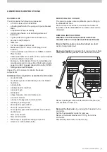
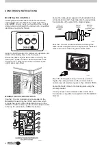
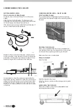
CONVERSION INSTRUCTIONS
REMOVAL INSTRUCTIONS
WARNING: ELECTRICAL WORK MUST ALWAYS BE
CARRIED OUT BY A QUALIFIED ELECTRICAL WORKER
Ensure that the cooler cannot be turned on
whilst
work is being carried out.
Remove all pads
(side panels) from cooler and put them
safely aside allowing access to the inside of the cooler.
ILL725-A
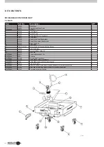
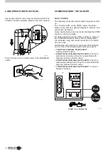
PACKING LIST
This kit contains the following components:
•
a 100 litre tank with wheels fitted,
•
a floating platform for the pump, with pump bracket
fitted.
• a replacement hose assembly
• cord storage hooks, cord restraint glands and
fasteners,
• a grille outlet and a grille frame and fasteners
• pop rivets and fasteners.
• cable ties.
• 1/2” brass nipple and lock nut.
•
Mains lead 3 pin 13 amp x 6m (fit plug to suit
location)
•
Communications Lead 6 Pin 1.5m CPMD to Switch
Plate Control
• Cable Gland 20mm to seal the 1.5m communications
lead hole drilled in the cooler
•
Enclosure, Cable Glands 16mm, Terminal Strip and
mounting screws for connection of field wiring mains
power to an IEC plugged cable to fit into the CPMD.
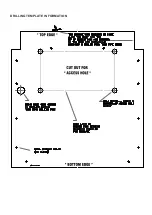
• Drilling and cutout Template
Unpack the kit to ensure it contains the above
components.
Additional items required to assemble the kit include;
• an electric drill,
• an electric jig saw or alternatively a narrow bladed
hand saw,
• a sharp knife,
• a philips head screwdriver,
• a pop-rivet gun,
• sandpaper,
• a tape measure, ruler and marker pen.
• a vacuum cleaner,
• a bucket of soapy water and clean loth,
• masking or packing tape,
•
20mm (3/4”) spade drill bit
•
25mm (1”) spade drill bit
•
16mm (5/8”) spade drill bit (Australia, South Africa
and Europe)
•
3mm (1/8”) drill bit
•
5mm (3/16”) drill bit
•
Teflon tape or approved sealing compound.
• scissors or a sharp blade knife,
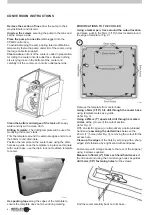
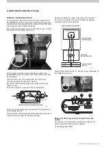
MODIFYING THE COOLER
The cooler requires some modification prior to fitting to
the MobileMAX Tank.
Some components will be removed and set aside for
later fitment to the MobileMAX Tank while others will be
discarded.
Remove packaged components located in the fan area
and set aside for later use.
Remove the float valve
by undoing the threaded in-line
connector.
Set the float assembly aside for later use.
Remove the plastic washer and “O”ring from inline
connector.
Discard the plastic inline connector only.
Summary of Contents for MobileMAX Series
Page 15: ...DRILLING TEMPLATE INFORMATION ...