background image

v2.2   7/28/11 

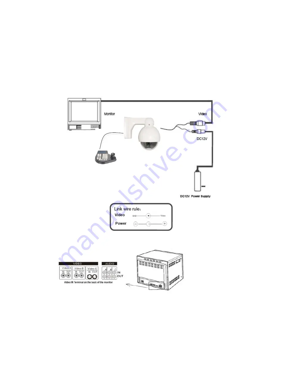
4.  WIRING CONNECTIONS 


a.  Connect the power supply’s DC plug to the camera’s power outlet. 
b.  Connect the camera to the monitor with a 75

Ω

 coaxial video cable. 

c.  Connect  unshielded  twisted  pair  (UTP)  control  cable  between  the  camera’s  RS485 

port and the PTZ controller. Be sure wire polarities are the same at each connection. 
The camera’s violet wire (A) is + positive and the white wire (B) is – negative. 

d.  Connect power supply’s AC plug to a suitable AC power outlet. 
e.  Adjust the lens direction according to the required surveillance area and environment. 


Summary of Contents for ST-WD600PTZMINI

Page 1: ...v2 2 7 28 11 1 INSTALLATION MANUAL ST WD600PTZMINI Vandalproof Intelligent Dome PTZ Color Camera ...

Page 2: ...ll settings in non volatile memory The camera features include a 5mm 15mm varifocal lens SPECIFICATIONS ST WD600PTZMINI Specifications Typical 1 Image Sensor 1 3 SONY Super HAD CCD II 2 Resolution 600TVL 3 Lens 5mm 15mm auto focus lens 4 Effective Picture Elements 811x508 5 Minimum Illumination 0 001 Lux 6 Scanning System 2 1 interface 7 Video Output 1 0VP P 75Ω 8 Signal to Noise Ratio 48dB 9 Sync...

Page 3: ...ables b To help ensure the camera s life and proper operation do not point the camera towards the sun or strong light c Do not install the camera in an environment where the temperature is above 113 F d Do not install the camera near a magnetic field or a high power motor e Do not mount the camera near a radiator or heater f Only use a dry cloth to clean the camera If there is dirt that is difficu...

Page 4: ...ct unshielded twisted pair UTP control cable between the camera s RS485 port and the PTZ controller Be sure wire polarities are the same at each connection The camera s violet wire A is positive and the white wire B is negative d Connect power supply s AC plug to a suitable AC power outlet e Adjust the lens direction according to the required surveillance area and environment ...

Page 5: ...tches 1 2 3 4 5 6 Camera No DIP Switch Setting Camera No DIP Switch Setting 1 1 0 0 0 0 0 17 1 0 0 0 1 0 2 0 1 0 0 0 0 18 0 1 0 0 1 0 3 1 1 0 0 0 0 19 1 1 0 0 1 0 4 0 0 1 0 0 0 20 0 0 1 0 1 0 5 1 0 1 0 0 0 21 1 0 1 0 1 0 6 0 1 1 0 0 0 22 0 1 1 0 1 0 7 1 1 1 0 0 0 23 1 1 1 0 1 0 8 0 0 0 1 0 0 24 0 0 0 1 1 0 9 1 0 0 1 0 0 25 1 0 0 1 1 0 10 0 1 0 1 0 0 26 0 1 0 1 1 0 11 1 1 0 1 0 0 27 1 1 0 1 1 0 12 ...

Page 6: ...v2 2 7 28 11 6 6 SETTINGS USING CAMERA s ON SCREEN DISPLAY MENU ...

Page 7: ...to return to Home Point 82 Disable auto return to Home Point 92 Set Left Limited Point 93 Set Right Limited Point 94 Reset Original Point 240 Clean Setup 241 Initialize System 242 Start PATTERN Setup 243 End PATTERN Setup 247 Start PATTERN 248 Stop PATTERN Clear Preset Point Numbers Preset No Function 1 32 Clear Preset Point 62 Clear Left Limited Point 63 Clear Right Limited Point 76 Clear Home Po...

Page 8: ...ing ripple and if so make the necessary adjustments c The picture background continuously changes color a fluorescent lamp s magnetic field may cause color roll therefore reduce the number of fluorescent lamps or increase the distance between the camera and the lamps d The picture appears smeared i the power supply voltage level may be unstable therefore try another power supply ii ensure the cabl...

Reviews: