background image

V2.0 7-31-12 


10 


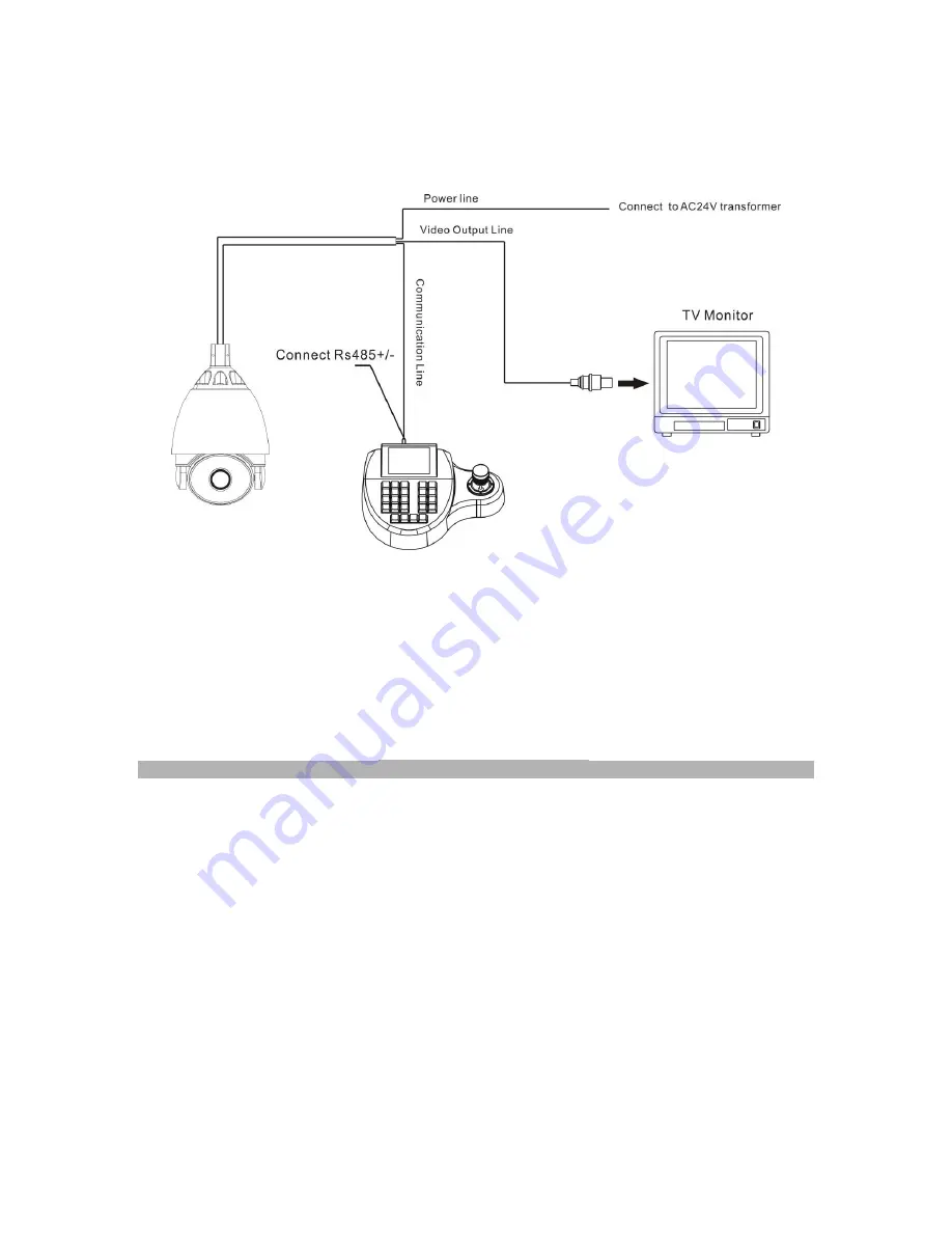
5.  WIRING CONNECTIONS 


6.  FUNCTIONS and OPERATION 


Menu Operation 
 

Several functions can be accessed direc

tly without using the camera’s on screen menu display. 

Note the following dedicated preset functions: 


Special Use Preset Numbers 

Call

 PRESET 95 

―― Enter into main OSD menu 

Call

 PRESET 96 

―― Run pattern 1 

Call

 PRESET 97 

―― Run Sequence 1 


Call

 PRESET 92 

―― Set Left limit point for L/R scan 

Call

 PRESET 93 

―― Set Right limit point for L/R scan 

Call

 PRESET 99 

―― Run Left-right scan 


NOTE: If Left limit point and Right limit point are set to the same position, calling preset 99 
will execute a 360° scan. 


Call 

PRESET 33 

―― Swing 180° 

Call

 PRESET 34 

―― Return to Zero point 

 
The on screen menu provides access to all camera functions through the use of a standard RS485 
connection and PTZ controller. 
 
As shown above, use the PTZ controller to CALL PRESET 95 and the ca

mera’s OSD menu will 

appear overlaid upon the video output of the camera, as shown below. 
 

Summary of Contents for ST-PTZIR480-30X

Page 1: ...INSTALLATION MANUAL ST PTZIR480 30X High Speed Intelligent Dome IR PTZ Color Camera Copyright North American Cable Equipment Inc ...

Page 2: ... the camera to continue previous functions after power is restored Support for 200 presets and 4 preset tours each containing up to 32 presets 4 patterns each can be recorded for 1000 discrete PTZ controller moves Support for 4 auto scans Soft and hard ID settings can be edited on the DIP switch or via the OSD menu Integrated multi protocol control PELCO P PELCO D 2 ch alarm input 2 ch alarm relay...

Page 3: ...ion Display Yes 14 Pan Tilt Position Display Yes 15 MAX IR Distance 330ft 19 Patterns 4 programmable pan tilt zoom and each tour is 120 seconds 20 Sequences Tours 4 programmable dwell time speed preset point 21 Protocol Pelco D Pelco P selectable 22 Auto Scan With programmable variable speed 23 High Efficient 3 Dimension Scan Yes 24 Long Focus Speed Limited Yes 26 Home Position Yes 27 Camera Menu ...

Page 4: ...Dimensions Wall Mount Dimension Picture 2 6 7 5 5 6 10 1 8 4 1 8 6 4 1 8 6 1 8 3 5 ...

Page 5: ...ssembled factory tested Ensure that all accessories are removed from the container before discarding packing materials a Use the mounting arm as a template to mark the holes for your mounting hardware This symbol is intended to alert the user to the presence of important operating and maintenance servicing instructions This symbol is intended to alert the user to the presence of uninsulated danger...

Page 6: ... towards the sun or strong light c Do not install the camera in an environment where the temperature is above 122 F d Do not install the camera near a magnetic field or a high power motor e Do not mount the camera near a radiator or heater f The installation site and material must fully support the weight of the product g Only use a dry cloth to clean the camera If there is dirt that is difficult ...

Page 7: ...4 CAMERA SETUP BAUD RATE PROTOCOL SETUP DIP Switch Settings Baud rate Setting SW2 B7 B8 Protocol Setting SW2 B1 B2 ...

Page 8: ...DOME ADDRESS SETUP System Setup DIP Switch SW1 ON 1 OFF 0 ...

Page 9: ...V2 0 7 31 12 9 ...

Page 10: ... limit point for L R scan Call PRESET 93 Set Right limit point for L R scan Call PRESET 99 Run Left right scan NOTE If Left limit point and Right limit point are set to the same position calling preset 99 will execute a 360 scan Call PRESET 33 Swing 180 Call PRESET 34 Return to Zero point The on screen menu provides access to all camera functions through the use of a standard RS485 connection and ...

Page 11: ...TLE OFF ZOOM POSITION OFF DIRECTION INDICATOR OFF ENVIRONMNT INDICATORS OFF GLOBAL SETTING PAN TILT SETTING PRESETS SETUP SEQUENCE SETUP PATTERN SETUP AUTOSCAN SETUP HOME ACTION LENS PARAMETER EXPOSURE MODE WHITE BALANCE BACKLIGHT MODE DOME ID TITLE LANGUAGE SELECT CHANGE PASSWORD FACTORY DEFAULT SYSTEM RESTART SYSTEM INFOMATION INPUT CHANNEL 001 ALARM ACTION DISARM INPUT MODE NO ALARM LINKAGE OFF...

Page 12: ...ystem setting menu 4 Under SYSTEM SETTING choose DOME ID and press OPEN to confirm 5 Using the up down and left right PTZ controls enter the 12 character serial number shown at the top of the menu and press OPEN to move to the next menu 6 Enter the new dome ID and press OPEN The menu will show the new dome ID and prompt to press OPEN to accept 7 Set your PTZ controller to the dome s new address an...

Page 13: ...the OPEN key Input New Password will be shown on the screen Input the new password then re enter it once more to confirm Password Modification Succeed will be shown on the screen 7 CAUTION For security reasons there is no way for users to bypass or reset the password settings If a password is entered incorrectly or forgotten it will be impossible to access the camera s OSD menu In order to regain ...

Page 14: ...to exit immediately without saving DIGITAL ZOOM SETTING Procedure 1 Call preset 95 to enter the main menu 2 Use the up down PTZ controls to choose CAMERA PARAMETERS and press OPEN to confirm the selection then enter the LENS PARAMETER menu 3 Under LENS PARAMETER choose DIGITAL ZOOM and press OPEN to confirm the selection and enter electronic zoom set The setting will blink 4 Up Down P T to choose ...

Page 15: ...e Mode menu choose the EXPOSURE MODE line item and press OPEN to confirm the selection and enter the exposure mode selection setting EXPOSURE MODE The 5 available choices are 1 IRIS 2 SHUTTER 3 BRIGHT 4 USER and 5 AUTO When the exposure mode is set to AUTO all exposure settings are handled by the camera automatically This is the recommended setting as several parameters are dynamically adjusted to...

Page 16: ...e gain settings can also be set manually CAMERA PARAMETERS WHITE BALANCE WHITE BALANCE SETTING Procedure 1 Call preset 95 to enter the main menu 2 Choose CAMERA PARAMETERS and press OPEN to confirm the selection 3 Choose WHITE BALANCE and press OPEN to confirm the selection and enter the white balance menu settings 4 The WHITE BALANCE parameters can be set as bellow AUTO This is the default mode W...

Page 17: ...rtically after the tilt is positioned straight down This allows the camera to operate as if it had 180 vertical tilt capability Procedure 1 Call preset point 95 to enter the main menu 2 Under PANTILT SETTING choose the PANTILT SETTING sub menu and press OPEN to confirm the selection 3 Under PANTILT SETTING choose AUTO FLIP and press OPEN to confirm the selection LENS PARAMETER EXPOSURE MODE WHITE ...

Page 18: ... selection and enter pan parameter set 3 Under PANTILT SETTING choose the JOYSTICK RECOVER menu and press OPEN to confirm the selection 4 Up down P T to change the setting 5 Press the OPEN key to save and exit Press the CLOSE key to exit directly without saving SPEED PROPORTIONAL This function causes the speed at which the camera pans to decrease proportionately with the amount of zoom applied Whe...

Page 19: ...ose the PANTILT SETTING menu press OPEN to confirm the selection and enter pan parameter set 3 Under PANTILT SETTING choose SET NORTH DIRECTION menu and press OPEN to confirm the selection and prepare to aim the camera 4 Use the PTZ controller to aim the camera lens to the North 5 Press the OPEN key to save and exit Press the CLOSE key to exit directly without saving GOTO ZERO POSITON This functio...

Page 20: ...racters of the preset name 3 Press the OPEN key to save and exit Press the CLOSE key to exit directly without saving SET NEW PRESET Procedure 1 Call preset point 95 to enter the main menu 2 Up Down cursor to choose PANTILT SETTING press OPEN to confirm the selection and enter pan set menu 3 Under PANTILT SETTING choose PANTILT SETTING menu press OPEN to confirm the selection 4 Under PANTILT SETTIN...

Page 21: ...rst point will blink indicating it can be changed 4 Use the Up down and L R PTZ controls to assign a preset for each step of the sequence If a preset is not assigned to a step the sequence will skip that step 4 Once all steps are set press the OPEN key to save and exit Press the CLOSE key to exit directly without saving Note Each group of parameters has two numbers the first represents the preset ...

Page 22: ...all preset point 95 to enter the main menu 2 Use the Up Down cursor to choose PANTILT SETTING and press OPEN to confirm the selection and enter pan set menu 3 Under PANTILT SETTING choose AUTOSCAN SETUP and press OPEN to confirm the selection 4 Under AUTOSCAN SETUP press AUTOSCAN NUMBER and choose 1 of the 4 autoscan routes to be edited Use the Up down P T to choose a scan route 5 Press the OPEN k...

Page 23: ... scans or 4 patterns PANTILT SETTING HOME ACTION HOME TIME Procedure 1 Call preset point 95 to enter the main menu 2 Use the Up down cursor to choose PANTILT SETTING choose HOME ACTION item and press OPEN to confirm the selection 3 Under HOME ACTION choose HOME TIME item and press OPEN to confirm the selection and enter into the home time setting item 4 Use Up down P T to modify the delay time fro...

Page 24: ...tle will be displayed on the OSD for that amount of time then it will stop being displayed and not be displayed again until a PTZ command is received from a controller 4 Press the OPEN key to save and exit Press the CLOSE key to exit directly without saving Note Preset Title Zoom Position Direction Indicator and Environmental Indicators are all set using the same method as Dome Title GLOBAL SETTIN...

Page 25: ...ss OPEN to confirm the selection 4 Use the Left right P T controls to choose arming or disarming the alarm function 5 Press the OPEN key to save and exit Press the CLOSE key to exit directly without saving INPUT MODE Setting Methods NC Normally Closed The normal alarm off state of the input is a closed circuit Opening the circuit triggers the alarm NO Normally Open The normal alarm off state of th...

Page 26: ...or use with the alarm outputs can be configured for N O operation Procedure 1 Call preset point 95 to enter the main menu 2 Use the Up Down cursor to choose ALARMS SETUP and press OPEN to confirm the selection and enter alarm set items 3 Under ALARMS SETUP choose one of the 2 alarm inputs to link to a relay AUX output 4 Select RELAY OUTPUT and press OPEN to confirm the selection 5 Use the Up Down ...

Page 27: ...een the camera and any fluorescent lamps in the vicinity d The picture appears smeared i The power supply voltage level may be unstable Try another power supply ii Ensure the cables are correctly connected and of the right impedance e Other interference may require the use of a SecurityTronix ground loop isolation filter f Power is on but the controller does not work i Check to make sure the DIP s...

Reviews: