background image


Maintenance

UR46-81/82S

Document number: SG104148TEN

Revision: B01

Issue date: 20.8.2012

 Copyright© 2012 Sécheron SA - This document is not contractual and contains information corresponding to the level of technology at the date of release.

D-38

File: d-UR46-8S_maint_en.fm

D.7.2

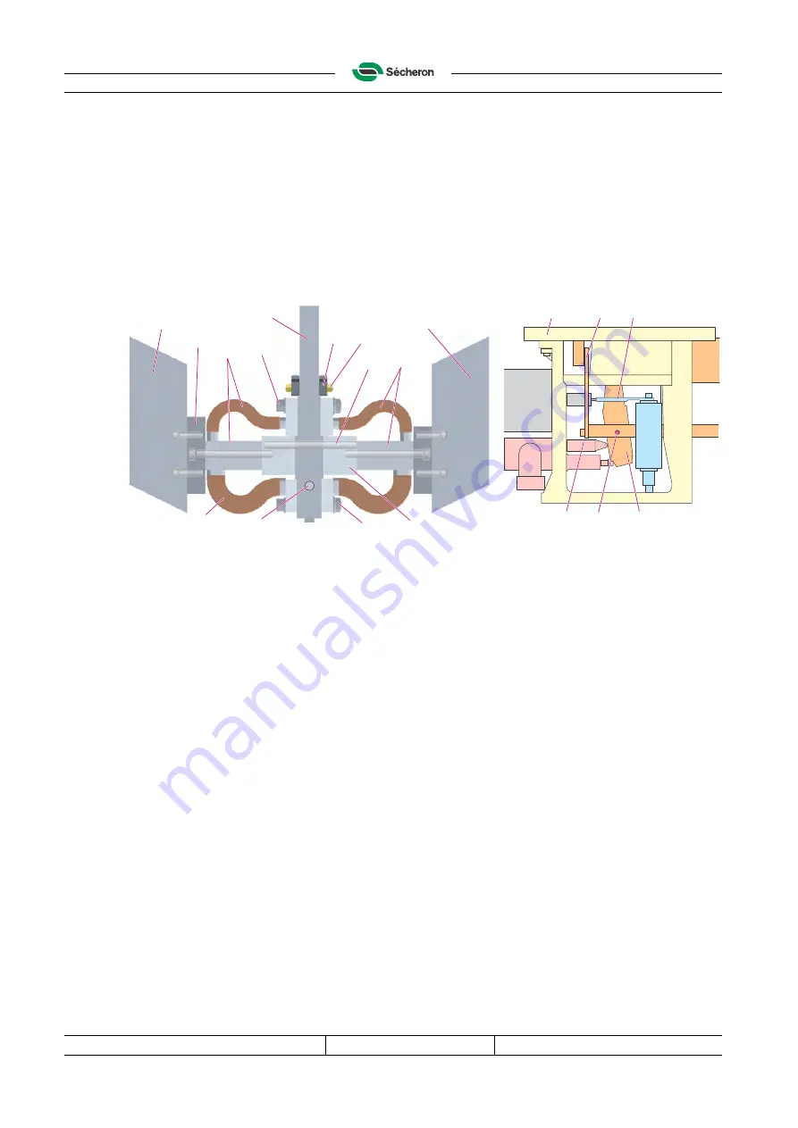
Replacement of the moving contact

Disassemble

a) Remove the coolers (34) and the plates (35).

b) Remove both flexible connections (15).

c) Remove the catches (18) with the pins and threaded nut rod by unscrewing one of the

nuts (19).

d) Remove the end of the pusher (21) from its seat (22) on the moving contact.

e) Push the pin (23

)

 out of the moving contact (17).

f)

Remove the moving contact (17) through the top plate (24).

04628-S

Reassemble

g) Insert the new moving contact (17) through the top plate (24) between both pawls of the

fork (25). Lightly grease the fork and the moving contact catches.

h) Insert the pin (23

)

.

i)

Insert the end of the pusher (21) into its seat (22) on the moving contact.

j)

Reassemble new catches (18) with the pins, threaded nut rod and both nuts (19).

k) Connect the flexible connections (15) with the thicker flexible connections (42) underneath:

first onto the top part, then onto the lower part and finally onto the lower connecting bar (16).

l)

Refit the plates (35) and the coolers (34).

D.7.3

Reassemble the metal strips, the pole and the fixed contact

Refer to both figures above.

Assemble the metal strips

a) Insert new metal strips (30): align the metal strips holes (31) with the top plate (24) holes.

Assemble the pole

b) Insert the blow-out core (13) into the new pole (12).

c) Insert this assembly correctly into the circuit-breaker, hold it against the rib of the frame (24)

to place and tighten the flange (10).

d) Assemble both straight connections (9) onto the connecting plate (11) and the flexible

connections (15).

e) Insert the M8 screw (8) into the frame plate (24) and fasten the pole (12) with the thin M8

nut (3; tightening torque of 17 Nm) and spring washer (4).

f)

Fit the flange (2) and hand tighten the M8 nut and washers.

15

35

34

34

14

17

14

22

42

16

15

19

18

23

17

23

25

24

9

21

Summary of Contents for UR46-81S

Page 1: ...igh speed circuit breaker UR46 81 82S Number of pages 68 SG104148TEN B01 Established by Desbaillet Checked by Released by Signature Date Secheron r r i i m I Lfc f J I 1 flKv C r Checked by i ft i l A Released by SG104148TEN B01 Established by Desbaillet W oLlL Signature i lo oiv n Ztf P lO fZ Date ...

Page 2: ...sh one is the only legal version It is important to keep this manual for the lifetime of the equipment and to pass it on to any subsequent owner or user Structure of this instruction manual Chapters A to F all the information needed to understand install use perform the mainte nance and order a spare part for the standard version of this device Chapter G Options all the information needed to under...

Page 3: ...nged text D 8 2 D 9 D 11 removed Molycote G 1 2 added and the lever 9 changed drawing G 1 3 added G 3 added kit number G 3 1 G 3 2 added stroke G 3 1 G 4 1 G 6 added important And many small updates throughout the manual B01 20 8 12 Desbaillet A 2 added safety rules B 3 modified C 1 modified all C 8 added C 12 1 added C 13 2 changed drawings modified values C 15 C 16 added D 1 changed all D 2 adde...

Page 4: ...EN Revision B01 Issue date 20 8 2012 Copyright 2012 Sécheron SA This document is not contractual and contains information corresponding to the level of technology at the date of release 4 File 2 UR46 8S_rev_en fm This page intentionally left blank Secheron ...

Page 5: ...equirements for the installation A 12 A 2 3 Hazard information A 13 A 2 4 Personnel use requirements A 13 B Technical specifications B 1 Characteristics B 15 B 1 1 Breaking current parameters B 15 B 1 2 Main circuit B 15 B 1 3 Control circuit B 15 B 1 4 Operating conditions B 15 B 2 Breaker control B 16 B 2 1 Typical values for the closing coils B 17 B 3 Auxiliary contacts B 18 B 3 1 Commutation d...

Page 6: ...2 D 5 1 Arc chute removal D 32 D 5 2 Inspection D 32 D 5 3 Arc chute refitting D 32 D 6 Detailed inspection D 33 D 6 1 Cleaning the contact area D 33 D 6 2 Measuring the W contact wear dimension D 33 D 6 3 Check and adjustment of the X clearance D 34 D 6 4 Check and adjustment of the Y clearance D 35 D 6 5 Check and adjustment of the Z clearance D 36 D 6 6 Check and grease D 36 D 7 Replacement of ...

Page 7: ...ing device F 54 F 4 3 Auxiliaries F 54 F 4 4 Direct tripping device F 55 F 4 5 Frame and accessories F 55 F 4 6 Arc chute F 56 G Options G 1 Manual closing device G 57 G 1 1 Description G 57 G 1 2 Maintenance G 57 G 1 3 Spare part catalogue G 57 G 2 Over current release indicator contact wear indicator G 58 G 2 1 Description G 58 G 2 2 Maintenance G 58 G 2 3 Spare and wear parts catalogue G 58 G 3...

Page 8: ...e G 63 G 6 1 Description of the vertical mechanical release G 63 G 6 2 Installation Prerequisites G 63 G 6 3 Installation Adjust the J clearance G 63 G 7 Varistor G 64 G 7 1 Description G 64 G 7 2 Trouble shouting G 64 G 7 3 Spare parts catalogue G 64 G 8 Direct release type DE G 65 G 8 1 Description G 65 G 8 2 Maximum current release Id settings G 65 G 8 3 Maintenance G 65 G 8 4 Spare and wear pa...

Page 9: ...g frame made of glass fibre reinforced insulating material 2 Main circuit consisting of a lower connection terminal 21 a moving contact 22 an upper connection terminal 23 and a fixed contact 24 3 Over current release 4 Arc chute 5 Closing device and fork 6 Auxiliary contacts housing with pusher 7 8 Coolers A 1 2 Uses of the high speed circuit breaker Because of its short response time following th...

Page 10: ... is closed the contact pressure is maintained by the closing device 1 either with a reduced holding current E type or with a permanent magnet M type Opening The circuit breaker opens either through an over current release or through an appropriate opening order An over current that exceeds the maximum current setting value causes the direct release rod 7 to move up which lifts 8 the fork 2 thus re...

Page 11: ...asic health and safety regulations of the European Economic Area EEA 03653 A 1 6 Routine tests These tests define the particular characteristics that each device has to fulfil at the end of the production These values are recorded in a routine test sheet which is attached to the device at delivery 1 Device type 6 International standards number 2 Identification number 7 Rated voltage 3 Serial numbe...

Page 12: ...e circuit breaker must be performed with the power off and the circuit breaker earthed Some controls require the use of low voltage DC electrical supply Follow the safety requirements in force to carry out these operations When performing installation inspections and maintenance keep your hands away from moving parts during the opening and closing operations of the circuit breaker Do not attempt t...

Page 13: ...egulations with experience of similar types of installations They must have proven skills in reading and working with drawings and cable lists as well as knowledge of local safety regulations for power and automation Work with the elec trical equipment must be performed by skilled or instructed technicians only A skilled person is an individual with technical knowledge or sufficient experience ena...

Page 14: ...evision B01 Issue date 20 8 2012 Copyright 2012 Sécheron SA This document is not contractual and contains information corresponding to the level of technology at the date of release A 14 File a UR46 8S_Intr_en fm This page intentionally left blank Secheron ...

Page 15: ...cuit Refer to the corresponding data sheet for complementary information B 1 3 Control circuit B 1 4 Operating conditions Unit UR46 81S UR46 82S Rated voltage UNe 900 V 1800 V Maximum operational voltage 1000 V 2000 V Rated insulation voltage UNm 3000 V 3000 V Rated service current INe 4600 A 4600 A Conventional free air thermal current Tamb 40 C Ith 4600 A 4600 A Rated short circuit making and br...

Page 16: ...tart of the closing pulse the contacts F G close B Closing pulse 0 5 to 1 s C Start of the holding current the contact G opens D Holding a R1 resistance limits the holding current to 5 of the closing current E Opening the contact F opens to provoke the interruption of the holding current 03602 Magnetic holding M type A Start of the closing pulse the contacts E close B Closing pulse 0 5 to 1 s then...

Page 17: ...ll wave voltage The total opening time with a recovery diode is 2 5 s not recommended as the opening time is too long Sécheron recommends to protect the control circuit while opening with a varistor Coil characteristics Closing E type holding M type opening Pulse 0 5 to 1 s Pulse 0 5 to 1 s U nom U min U max R nom I nom I min E I min M I max R1 Inom I min I max R s R p I nom I min I max V V V Ω A ...

Page 18: ...mutation diagram 03672 M Main contact A Switching of auxiliary contacts a b Number of auxiliary contacts 5a NO 5b NC in standard configura tion Rated voltage potential free contacts 24 to 220 Vdc Maximum breaking current Ohmic load at 110 Vdc Inductive load τ 15 ms at 110 Vdc 1 A 0 3 A Conventional thermal current Ith 10 A Minimum let through current at 24 Vdc For a dry and clean environment 10 mA...

Page 19: ...e DANGER To ensure maximum safety servicemen and operators must read the A 2 Safety precautions section before starting installation maintenance and adjustment of the device or before starting to operate it Weight 5 kg UR46 81S UR46 82S Circuit breaker standard without options 85kg 86 kg Arc chute 25 kg 34 kg Total 110 kg 120 kg 320 246 70 760 4xØ11 23 62 69 1 168 2 419 1 617 5 2 238 100 40 137 40...

Page 20: ... delivered devices with the order correct identification numbers on the identification plates and correct number of devices for any damage on devices C 3 2 Transport damage procedure If the equipment is damaged the customer must imperatively report the damage by an official letter to Sécheron SA within 7 days after receiving the goods Once this delay has expired all transport damages can no longer...

Page 21: ...er alloys aluminium rubber seals etc plastics electrical cables permanent magnets Recycle or dispose of all materials and components in compliance with local regulations C 8 Tightening torques C 8 1 General procedure Each screw nut needs to be tightened to a specific torque Torques that are different from the table below are indicated throughout this manual in their corresponding sections Put a ne...

Page 22: ...rcuit breaker by means of M10 screws 3 or bolts 4 with washers tightened to a torque of 44 Nm To be able to insert one of the screw 3 the earth bolt 5 needs to be removed and reassem bled after see C 11 04656 C 9 2 Clearances to be observed in operating position Grid with 50 of surface opening 04612 Important The circuit breaker must be installed in an indoor ventilated enclosure that is free from...

Page 23: ...with wire gauges 0 5 4 mm2 Note The number of the Harting s pins removal tool is 09 99 000 0319 b Manually insert the pins 6 into the holder 7 and fix the holder 7 into the connector 1 c Check that the fixed 3 and mobile 1 connectors are not damaged d Connect the mobile connector 1 into the fixed connector 3 ensuring the correct orienta tion pin 1 must go into hole 1 according to the wiring diagra...

Page 24: ...chnology at the date of release C 24 File c UR46 8S_inst_en fm C 11 Earth connection Connect the earthing conductor 1 onto the M8 connecting bolt 2 Tighten it to a torque of 22 Nm This bolt also connects the closing device 3 and the multi pole connector 4 to the earth 03615 CAUTION The minimal cross section of the earthing conductor 1 must be of 50 mm2 1 4 3 2 2 1 2 1 21 Secheron A 10mm S I U t H ...

Page 25: ...s 4 onto each main terminal 1 Tighten the bolts 4 to a torque of 50 67 Nm 04613 Note According to EN 50123 for this range of current the recommended current density is 1 A mm2 for copper bars and 1 3 A mm2 for copper cables C 12 1 Recommended dimensions of the bars cables 02764 According to EN 50123 for this range of current the recommended current density is 1 A mm2 for copper bars and 1 3 A mm2 ...

Page 26: ... shows the correspondence between the current values and the scale 8 Version with core Two ranges of setting are available With the core 11 inserted in the direct release 1 the setting range is according to label 9A between 2000 and 5000 A with corresponding scale 5 from 1 1 to 4 8 With the core 11 removed from the direct release 1 the setting range is according to label 9B between 4050 and 8000 A...

Page 27: ...uration set between 0 5 and 1 s followed by the holding current Holding current value in the case of an E type circuit breaker set at 5 of the closing current value b Ensure that both catches 1 of the moving contact are properly inserted in both grooves 2 of the fork unit 3 03617 S c Check that all fixing and connection bolts are correctly tightened d Check that the circuit breaker can close and o...

Page 28: ...ming from a voltage current detector corresponds to the information about the state of the circuit breaker given by its auxiliary contacts 1 according to the complete electrical circuit For example if the information coming from the auxiliary contacts of the circuit breaker shows that the circuit breaker is open and the voltage transformer detect a voltage this indicates a serious problem which mu...

Page 29: ...n and operators must read the A 2 Safety precautions section before starting installation maintenance and adjustment of the device or before starting to operate it 1 Open end wrenches 8 10 13 and 17 mm 2x24 2x27mm 4 mm thick 2 Pin removers 4 and 6 mm 3 Allen wrenches 2 5 3 4 5 6 and 8 mm 4 Ratchet wrench with sockets 8 9 10 and 13 mm 5 Flat head screwdrivers Nº 4 and 6 mm 6 Pozidriv screwdriver Nº...

Page 30: ...allowed Important These frequencies are given for normal abnormal conditions are listed in C 2 The user should adapt these frequencies when using this device in other condi tions Operation Frequency Visual inspection At least once a year Detailed inspection Whenever one of the following event occurs first Every 18 24 months Or after every 250 overload current interruptions current value maximum cu...

Page 31: ...1 Spark arresters When the marks left by local burns reach a depth that is half the part s original thickness or when cracks appear D 7 5806 F 4 6 Horns 81 Horns 82 When their cross section reaches half the part s original cross section 20 x 4 mm2 D 9 5802 F 4 6 5803 F 4 6 5804 F 4 6 De ionization plates When the marks left by local burns reach a depth that is half the part s original thickness 2 ...

Page 32: ...heck that all components such as bolts nuts clips etc are present If needed replace them and tighten them according to the table of the D 2 except for specifically specified torques in corresponding paragraphs throughout this manual b Check the following parts for wear 1 according to the D 4 Part replacement criteria and their referenced sections the moving contact 2 the fixed contact 3 the pole 4...

Page 33: ...he cut out chamber and the arc chute inlet 1 d Refit all components 04623 S D 6 2 Measuring the W contact wear dimension Two different methods can be used Use the method 1 when the lateral access to the main contacts is possible The circuit breaker must be closed Method 1 a Remove a spark arrester 1 b Using a flexible graduated ruler 2 measure the W1 distance between the base of the fixed contact ...

Page 34: ...rted between the mobile and the fixed contacts to block the contacts in the open position 04638 S b Checking the X clearance two possible ways Measure the extension of the rod 2 out of the closing device 3 with a depth gauge or a comparator First without pressure on the rod 2 measure the length A Second with pressure 6 applied axially onto the rod 2 press the fork 4 against both catches 5 measure ...

Page 35: ...n both arms 6 of the fork with the recommended Sécheron s Y gauge or a feeler gauge Where there is a difference between the sides take the average value Y Y1 Y2 2 Adjustment Loosen the lock nut 1 and the nut 2 turn the nut 2 to adjust the Y clearance and retighten the nut 1 After adjustment at least two open closing operations must be performed prior to re check the clearance Note Control and adju...

Page 36: ...d position Note If the optional Position Indicator is mounted on the housing 9 see G 9 b Remove the transparent cover 5 c Measure the Z clearance at the tip of the pusher 8 using the recommended Sécheron s Z gauge or an universal feeler gauge Adjustment Loosen the lock nut 7 and nut 6 turn the nut 6 to adjust the Z clearance and retighten both After the adjustment at least two open closing operati...

Page 37: ...rt 40 b Remove the flanges 2 the thin M8 nuts 3 and the spring washers 4 Fixed contact c Lift up the end 6 of the fixed contact 5 to free it from the threaded rod 7 d Simultaneously loosen both nuts 27 to release the fixed contact 5 and remove it 31 from above Pole e Remove the screw 8 Note For the UR46 81 version only and if the blowing device is present loosen the screws 42 and remove the coil 4...

Page 38: ...n the moving contact j Reassemble new catches 18 with the pins threaded nut rod and both nuts 19 k Connect the flexible connections 15 with the thicker flexible connections 42 underneath first onto the top part then onto the lower part and finally onto the lower connecting bar 16 l Refit the plates 35 and the coolers 34 D 7 3 Reassemble the metal strips the pole and the fixed contact Refer to both...

Page 39: ... the blowing device is present For UR46 81 version only reassemble the coil 41 Insert the electrode support 40 into its seat into the main frame and insert the electrode 39 Connect the cable 38 Assemble both magnetic cheeks 37 n Insert the spark arresters 1 into their seats D 7 4 Refit the arc chute See D 5 3 Arc chute refitting D 8 Replacement of the fork unit a Remove the closing device see D 10...

Page 40: ...e by one e Re insert the baffles 4 and the de ionizing plates 5 one by one replacing the worn parts according to D 4 Part replacement criteria f Press the arc chute walls 3 together and tighten the six bolts 2 do not forget the washers 04636 S D 9 2 Replacement of the horns a Lay the arc chute 1 on a bench b Loosen the bolts 2 and spread 5 the lower part of the arc chute walls 3 c Remove the horns...

Page 41: ...ns properly in place when released h Check the X and Y clearances and adjust them if necessary see D 6 3 and D 6 4 i Connect both or the four for 24 V coil wires 1 with the blue one on the left j Connect the earth connection 2 using both M6 screws k Slightly grease the fork 5 and the catches 7 D 11 Replacement of the closing core and the spring a Remove the closing device 1 see D 10 Replacement of...

Page 42: ...me 11 and the direct release 8 To have this bar in the correct position the groove 12 must be upside Screw in the screws 5 and hand tighten them i Insert the isolations 19 20 between the bar 6 and the support 21 screw in the screw 18 and hand tighten it j Insert the moving contact 1 see D 7 2 Replacement of the moving contact and insert its pin 14 The moving contact 1 must be located in the centre...

Page 43: ...t 7 e Insert the end 3 of the pusher into its seat on the moving contact 5 f Check that the swivel joint support 6 is at the bottom of its seat 7 g Adjust clearance Z see D 6 5 Check and adjustment of the Z clearance h Reconnect the connector 1 and the earth connection 2 Shock absorber a Remove the connector 1 and the earth connection 2 b Remove the unit 9 from its frame seat 10 c Remove the shock...

Page 44: ...vision B01 Issue date 20 8 2012 Copyright 2012 Sécheron SA This document is not contractual and contains information corresponding to the level of technology at the date of release D 44 File d UR46 8S_maint_en fm This page intentionally left blank Secheron ...

Page 45: ...g device type mounted on the circuit breaker DANGER To ensure maximum safety servicemen and operators must read the A 2 Safety precautions section before starting installation maintenance and adjustment of the device or before starting to operate it Defect Possible causes Remedies Over heating Dirty or damaged worn or burnt contacts Clean or change the main contacts see D 7 Loose main conductor co...

Page 46: ...esistor see B 2 1 Insert Rp if needed see B 2 3 Check if the closing coil has been dismantled In that case it may have been improperly set when reassembled adjust the gap according to E 2 procedure 3 Do not change settings made by Sécheron DEFECT CAUSE REMEDY C The device does not maintain its closed position Closing current too low Imin 1 Check the power of the alternating current source 2 Charge...

Page 47: ...stment is satisfactory carry out the following test close the circuit breaker disengage the fork 6 from the catches 7 transmit an off order to the closing device if it does not return to rest see defect B for M type or D for E type in the above tables Procedure 2 This procedure increases the gap on the E type closing device reduces the gap on the M type closing device a Mark 1 the position of the ...

Page 48: ...nd tighten the four screws 5 to a torque of 9 Nm e Mark the cover 2 with a extension of the marking 10 on the body 4 to indicate the posi tion of the flange 9 03643 E 3 Performance check See the trouble shooting sheets for M or E type if one of the functions is not carried out during the test a Close the circuit breaker and check the closing current the holding current E type b Trip the circuit br...

Page 49: ...n sheet 4 and continue until you find the defective switch by testing them with an electric multi meter d Mark and disconnect the 3 or 4 wires and replace the defective switch e Connect the wires Note To wire the 5U type 3 wires reversing contacts remove the connection 6 from the old switch 3 and refit it on the new switch f Replace the switches 3 and insulation sheets 4 in the reverse order to wh...

Page 50: ...evision B01 Issue date 20 8 2012 Copyright 2012 Sécheron SA This document is not contractual and contains information corresponding to the level of technology at the date of release E 50 File e UR46 8S_trouble_en fm This page intentionally left blank Secheron ...

Page 51: ...the correct ones if your device have optional parts that override these parts in that case the correct part numbers can be found in the Options or Customization chapters F 2 Recommended spare parts In addition to the wearing parts we recommend to keep in stock some parts that could be damaged by inadequate operations Depending on the quantity of devices in operation we recommend the following numb...

Page 52: ...1KV 18x1x193 MU METAL 1 1192 HSBA300168P46001 x CONNECT 20x6x341 5 UR46 POLE 1KV CU 1 UR46 82S 25 SG100017P3 x SHEET 249x18x1 RIGHT 2KV MU METAL 1 26 SG100017P4 x SHEET G 2KV 18x1x285 MU METAL 1 1192 HSBA300168P46002 x CONNECT 20x6x435 UR46 POLE 2KV CU 1 Common parts 2 HSHR330085R46001 x CONTACT FIXED UR46 1KV 1 HSHR330085R46002 x CONTACT FIXED UR46 2KV 1 130 HSBA300158R46001 x BLADE WITH CATCH UR...

Page 53: ... only for HSCB without blowing device 142 HSBA300172R46002 x CONNECT FLEX UR46 RIGHT ASM 1 1196 HSBA331202P0001 x ANTI SPARK PL 138x119x21 3 BMC 2 In case of presence of the blowing device 1196 SG102106P00001 x ANTI SPARK RIGHT 137 5x122x21 3 UR346 EBOD BMC 1 1197 SG102107P00001 x ANTI SPARK LEFT 137 5x122x21 3 UR346 EBOD BMC 1 1200 SG101868R00002 x BLOW OUT COIL E BOD STD 1 1201 SG102093P00001 x ...

Page 54: ... type E option HSBA100027R1400 x 125 250 V type M option 320 Body with coil HSBA200010R0700 24 48 V type E HSBA200010R0600 24 48 V type M HSBA200010R0900 32 64 V type E HSBA200010R0800 32 64 V type M HSBA200010R0500 36 72 V type E HSBA200010R0400 36 72 V type M HSBA200010R0300 110 220 V type E HSBA200010R0200 110 220 V type M 325 HZN451264P0008 WASHER SHIM 8 20x0 1 SP ST DIN988 HZN451264P1208 WASH...

Page 55: ...ear spare parts catalogue F 4 4 Direct tripping device 02683 F 4 5 Frame and accessories 110408 2 Pos Part number WP SP Description Qty 1200 DIRECT TRIPPING DEVICE 1 HSHR230035R0200 x 2 to 8 kA HSHR230035R0100 x 4 to 15 kA HSBA200070R0300 x 2 to 5 kA option HSBA200070R0400 x 4 to 10 kA option Pos Part number WP SP Description Qty 710 HSBA300028R0100 x PUSHER ASSEMBLY 1 720 HSBA400213P0001 x SHOCK ...

Page 56: ... parts 5802 HSBA231223P0001 x PLATE 301x229x12 3 UPPER DEIONIZER BMC 2 5803 HSBA231222P0001 x PLATE 164 5x119 5x5 8 LOWER DEIONIZ BMC 34 5804 HSBA231254P0001 x PLATE 164 5x119 5x7 6 DEIONIZ INF BMC 2 5805 HSBA432089P0001 x BAFFLE 119 5x2 5x119 5 ST U1203 37 5806 HSBA432105P0001 x HORN L 166x34x20 5 END CH 81 CU ETP 2 Arc chute type 82 parts 5802 HSBA231223P0001 x PLATE 301x229x12 3 UPPER DEIONIZER...

Page 57: ...ver 3 and insert the cylinder 6 with its spring 7 and insert the manual closing device 5 f Screw the unit together with the four M6 screws 1 taking care that the flange 4 does not move hold the cover 3 firmly in this position and turn the manual closing device 5 until the pivot 8 and the lever 9 can be operated vertically from top to bottom g Tighten the four M6 screws 1 to a torque of 9 Nm 03632 ...

Page 58: ...f times the circuit breaker is tripped by an overcurrent release The coil shaft moves a plate 3 and actuates the switch 4 each time the direct or indirect release is activated Contact wear indicator Attached to the rear of the closing coil 1 the contact wear indicator 2 indicates that the main contacts are reaching their maximum acceptable value for wear and must therefore be changed The coil shaf...

Page 59: ...ssible stroke of 20 mm G 3 2 Maintenance J clearance J 1 0 0 25 mm Note This measurement is taken with the circuit breaker closed Measure the J clearance between the fork 3 and the plate 2 using a feeler gauge If needed adjust the J clearance Adjustment a Loosen the screw 7 b Rotate 8 the shaft 2 until the proper J clearance is obtained Note The stroke K must be of 17 2 mm c Tighten the screw 7 Im...

Page 60: ...rotates 8 the plate 2 thereby lifting 6 the fork 3 and opening the moving contact 4 02652 2 Note The BIM5 and BIM6 indirect releases can be used as manual releases by pushing on the axle 1 end The force F needed to perform a manual release is 80 N The stroke of the axle 1 until the release point is 8 mm on a total possible stroke of 10 mm Fault Possible causes Remedies See Circuit breaker does not...

Page 61: ... G 5 for the procedure G 4 4 Maintenance In case of replacement of the direct release When removing the direct release in the D 12 remove either the complete BIM5 and BIM6 indi rect releases either only the axle 2 by loosing the screws 7 G 4 5 Troubleshooting See the G 3 3 G 4 6 Spare and wear parts catalogue 03673 Pos Part number WP SP Description Qty 1280 HSBA131233R00006 INDIRECT TRIPPING DEVIC...

Page 62: ...urement is taken with the circuit breaker closed G 5 1 Measurement Measure the J clearance between the fork 3 and the plate 2 using the recommended Sécheron s J IND or J M3 gauges If needed adjust the J clearance 02779 G 5 2 Adjustment a Loosen the screw s 7 b Rotate 8 the shaft 2 until the proper J clearance is obtained Note The stroke K must be of 17 2 mm c Tighten the screw s 7 03548 J 3 2 5 Im...

Page 63: ...rk 3 G 6 3 Installation Adjust the J clearance The J clearance is the operating clearance between the fork 3 and the plate 2 J 1 0 0 25 mm This procedure is performed with the circuit breaker closed a Loosen the screw 7 and move laterally the lever 12 in order to bring the rod 1 parallel to the frame 13 b Let the rod 10 go down until it lies onto the plate 11 c Rotate clockwise 8 the shaft 2 until...

Page 64: ...ice 2 opens G 7 2 Trouble shouting Remove both screws 3 to replace the varistor 1 as shown by the position label 4 Screws M4x6 flat washer 1 Nm tightening 03662 G 7 3 Spare parts catalogue The varistor type is determined according to the closing device voltage in the following table Coil voltage U VDC Battery Rectified with 2 half waves 24 SG101375R1 SG101375R1 36 SG101375R1 SG101375R00004 48 SG10...

Page 65: ...eans of the nut 1 and counter nut 2 which are tightened at the factory B The thin regulation by step of 200 A is performed by the customer on the side of the circuit breaker Loosen the nut 4 with a 19 mm flat key 7 Turn the screw 5 with a 5 mm Allen key 8 until the marker 6 reaches the desired value on the scale 3 turn clockwise to rise the lds value and counter clockwise to lower it Hold the scre...

Page 66: ... the rear of the auxiliary contacts 1 the position indicator 2 shows whether the circuit breaker is open or closed It is actuated by the pusher 3 When the indicator is red the circuit breaker is closed and when the indicator is green the circuit breaker is open 03661 Pos Part number WP SP Description Qty 1250 SG101522R0300 x SPRING TRIPPING DEVICE 2 5 kA 1 SG101522R0400 x SPRING TRIPPING DEVICE 4 ...

Page 67: ...s shown below using the following crimp contact tools from Cannon ITT Industries Crimping tool VM8 Crimping die VH435 Insertion tool 46736 Removal tool 43240 Guide pin for female contacts 27977 12T8 The closing coil is connected to pins 21 and 22 of the connector regardless of the polarity b Connect the moving connector 3 into the fixed connector 4 03614 Wiring between the auxiliary contacts and t...

Page 68: ...Secheron ...

Reviews: