5-42
5.3
Configuring the Switching Inputs (Alarm Inputs)
Introduction
Depending on its configuration a logger can be equipped with up to two switching
inputs (alarm inputs) which can be connected to active circuits. For each of these
inputs, it can be specified which input voltage value causes an alarm. An example of
such an alarm loop is shown in section 3.3.1.4.
As known from the channel configuration, an alarm can trigger up to two internal
relays.
Furthermore, alarm messages can be sent via SMS or email, if GSM connectivity
has been established and properly configured (see sections 3.2 and 5.4).
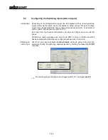
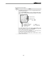
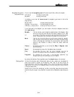
First of all, you have to activate the Alarm inputs which are going to be part of an
alarm input during the upcoming operation period by marking the respective On/Off
checkbox:
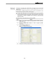
Activating an
alarm input
The switching input of single-channel loggers (LOG D-1) is always Input 2!
Summary of Contents for Sebalog D
Page 2: ......


