INSTALLATION (Continued)
5
LAWN SPRINKLING APPLICATION
This pump is designed for lawn sprinkling. It is designed to
deliver plenty of water at full sprinkler pressure. It can pump
from a pond, cistern or well points.
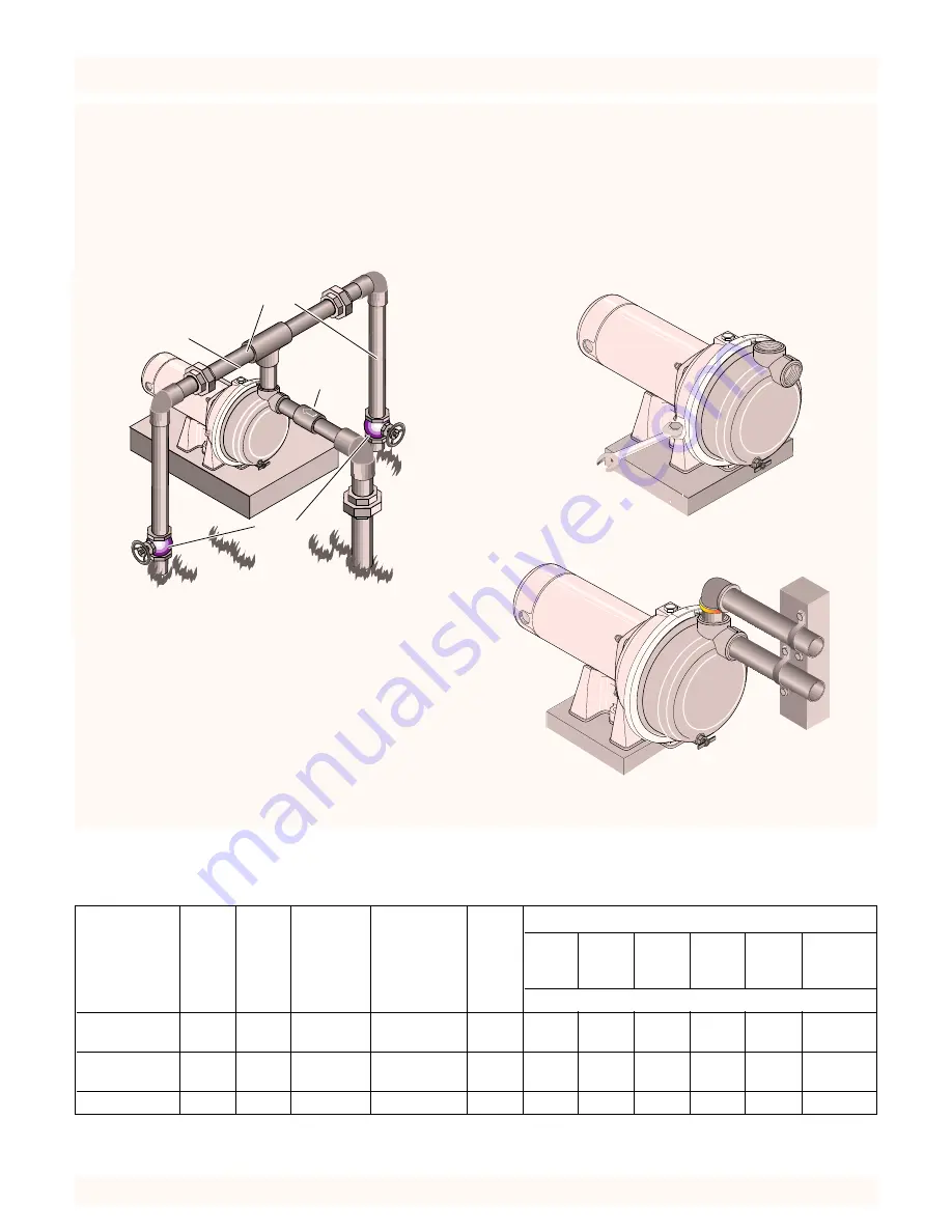
Pump discharge can be divided to supply two (2) or more
sprinkler systems. A suggested multiple discharge to service
is shown in Figure 3.
Do not use in a pressure tank or booster pump appli-
cation.
Pump/Piping Installation
PUMP INSTALLATION
NOTICE:
Use Teflon tape supplied with the pump for mak-
ing all threaded connections to the pump itself.
Do not use
pipe joint compounds on the pump:
they can react with
the plastic in the pump components.
1. Bolt pump to solid, level foundation.
2. Support all piping connected to the pump.
3. Wrap 1-1/2 to two layers of Teflon tape clockwise (as you
face end of pipe) on all male threads being attached to
pump.
4. Tighten joints hand tight plus 1-1/2 turns.
Do not over-
tighten.
NOTICE:
Install pump as close to water source as possible.
Long piping runs and many fittings create friction and re-
duce flow.
Use schedule 80 or iron pipe. See “Well Pipe Installation” for
more information.
P
846 0494
Gate
Valve
Check
Valve
To
Service
Priming
Plug
Figure 3 – Multiple Discharge
P
843 0494
P
841 0494
Figure 4 – Bolt Pump Down
Figure 5 – Independently Support All Piping
Attached To Pump
WIRING CHART
Recommended Wire and Fuse Sizes
DISTANCE IN FEET FROM MOTOR TO METER
Branch
0’
51’
101’
201’
301’
401’
Max.
Fuse*
Min.
TO
TO
TO
TO
TO
TO
Pump
Load
Rating*
Wire
50’
100’
200’
300’
400’
500’
Model
HP
Volt
Amps
Amps
Size
WIRE SIZE
115
14.8
20
12
12
12
8
6
6
4
390.262453
1
230
7.4
15
14
14
14
14
14
12
10
115
19.2
25
10
10
10
8
6
4
4
390.262553
1-1/2
230
9.6
15
14
14
14
14
12
10
10
390.262653
2
230
12.0
15
14
14
14
14
12
10
10
*Dual element or Fusetron time delay fuses recommended for all motor circuits.


