background image

6

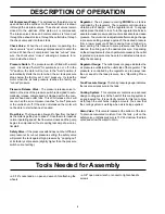
Air Compressor Pump:  To compress air, the piston moves
up and down in the cylinder.  On the downstroke, air is drawn
in through the air intake valves.  The exhaust  valves remain
closed. On the upstroke of the piston, air is compressed.
The intake valves close and compressed air is forced out
through the exhaust valves, through the outlet tube, through
the check valve and into the air tank.

Check Valve:  When the air compressor is operating, the
check valve is “open”, allowing compressed air to enter the
air tank. When the air compressor reaches “cut-out” pres-
sure, the check valve “closes”, allowing air pressure to re-
main inside the air tank.

Pressure Switch:  The pressure switch is fitted with a small
lever.  It is labeled "Auto/O" for automatic run or  off. In the
"O" position, the motor will not run. In the "Auto" position, it
automatically starts the motor when the air tank pressure
drops below the factory set “cut-in” pressure.  It stops the
motor when the air tank pressure reaches the factory set
“cut-out” pressure.

Pressure Release Valve:  The pressure release valve lo-
cated on the side of the pressure switch is designed to auto-
matically release compressed air trapped within the com-
pressor head and outlet tube. This short release of air will
occur when the air compressor reaches "cut-out" pressure
or the unit is shut off. If the air is not released, the motor will
not be able to start when next required.

Flow Valve:  The flow valve allows air to flow from the head
as the motor is getting “up to speed”. Once the motor reaches
normal operating speed, the flow valve closes and the pump
begins to compress air, thus requiring less amp draw on ini-
tial start.

Safety Valve:  If the pressure switch does not shut off the air
compressor at its cut-out pressure setting, the safety valve
will protect the tank against high pressure by “popping out”
at its factory set pressure (slightly higher than the pressure
switch cut-out setting).

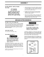
Tools Needed for Assembly

• a 9/16" socket and an  open end wrench for attaching the
wheels

• a 3/8" open end wrench or socket to tighten handle
screws

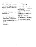
Regulator:  The air pressure coming FROM the air tank is
controlled by the regulator.  The regulator control knob is a
vibration proof design.  Lift the regulator knob  to engage
and depress the knob to lock. Turn the regulator knob clock-
wise to increase pressure and counter-clockwise to decrease
pressure. To avoid minor readjustment after making a change
in pressure setting, always approach the desired pressure
from a lower pressure. When reducing from a higher to a
lower setting, first reduce to some pressure less than that
desired, then bring up to the desired pressure.  Depending
on the air requirements of each particular accessory, the outlet
regulated air pressure may have to be adjusted while oper-
ating the accessory.

Regulator Gauge:  The outlet pressure gauge indicates the
air pressure available at the outlet side of the regulator.  This
pressure is controlled by the regulator and is always less
than or equal to the tank pressure. See “Operating Proce-
dures”.

Tank Pressure Gauge: The tank pressure gauge indicates
the reserve air pressure in the tank.

Cooling System:  This compressor contains an advanced
design cooling system. At the heart of this cooling system is
an engineered fan. It is perfectly normal for this fan to blow
air through the vent holes in large amounts. You know that
the cooling system is working when air is being expelled.

Drain Valve:  This valve is located at the bottom of the tank.
To drain accumulated moisture from the tank, pull on the
safety valve until tank pressure is 15 PSI. Unscrew the drain
valve and allow the water to drain.

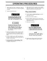
DESCRIPTION OF OPERATION

Summary of Contents for 919.72512

Page 1: ...e Number can be found on the bar code label on the rear of the air tank 3 The Serial Number can be found on the bar code label on the rear of the tank 4 The Tank Registration Number is located on the...

Page 2: ...raftsman Air Compressor warranty gives you specific legal rights and you may have other rights which vary from province to province Sears Canada Inc Toronto Ont M5B 2B8 WARRANTY 2 SAFETY GUIDELINES 3...

Page 3: ...cause the tank to rupture Modifications to the air tank will cause it to weaken Hot Parts The metal compressor components such as manifold tubes etc become hot when the air compressor is running If yo...

Page 4: ...do not use accessories that contain aluminum or galvanized parts You must either change the material you intend to spray or use only stainless steel spray equipment Certain materials you are spraying...

Page 5: ...ator gauges and handle This air compressor requires no oil Now you can enjoy all the benefits of having an air compressor without ever having to purchase add or change oil Your air compressor can be u...

Page 6: ...cut out pressure setting the safety valve will protect the tank against high pressure by popping out at its factory set pressure slightly higher than the pressure switch cut out setting Tools Needed...

Page 7: ...AND DOWN STAIRS OR STEPS THE UNIT MUST BE LIFTED OR PUSHED UP A RAMP This portable air compressor is equipped with a cord having a grounding wire with an appropriate grounding plug The plug must be u...

Page 8: ...number decreases 10 AWG and 8 AWG may also be used DO NOT USE 14 OR 16 AWG a three wire extension cord that has a three connector grounding plug and a three slot receptacle that will accept the plug...

Page 9: ...pressure reaches cut out pressure 5 Open the regulator by turning it clockwise Adjust the regulator to the correct pressure setting Your compressor is ready for use 6 Always operate the air compressor...

Page 10: ...pressor pull the ring on the safety valve to make sure that the safety valve operates freely If the valve is stuck or does not operate smoothly it must be replaced with the same type of valve Risk of...

Page 11: ...release valve when there is pressure in the tank and the com pressor is shut off Remove and clean or re place check valve DO NOT OVERTIGHTEN Air tank must be replaced Do not repair the leak Return com...

Page 12: ...tions Return to Sears Service Center for inspection or replacement if necessary Bleed the line by pushing the lever on the pressure switch to the O position if the valve does not open replace it Inspe...

Page 13: ...rdered from any Sears Service Center and most Sears stores If the parts you need are not stocked locally your order will be electronically transmitted to a Sears Repair Parts Distribution Center for h...

Page 14: ...quette appos e l arri re du r servoir d air 3 Le num ro de s rie indiqu sur l tiquette appos e l arri re du r servoir d air 4 Le num ro d enregistrement du r servoir indiqu sur la plaque signal tique...

Page 15: ...ion 10 Moteur 10 Entreposage 10 GUIDE DE D PANNAGE 11 SCH MA APPAREIL 13 LISTE DES PI CES 14 SCH MA BLOC COMPRESSEUR 15 LISTE DES PI CES BLOC COMPRESSEUR 16 NOTES 17 POURCOMMANDERLESPI CESDERECHANGE 1...

Page 16: ...que dans des locaux bienventil setd pourvusdevapeursd essenceoude solvant Nepasfairefonctionnerlecompresseurpr s des locaux de vaporisation Ne pas r gler ter ni modifier la soupape de s ret ni le pre...

Page 17: ...erlebecoulegicleurversunepersonne ou une partie du corps Toujoursporterdesgantsetdeslunettesprotectrices quand on utilise le compresseur d air Arr ter toujours le compresseur avant de brancher ou de d...

Page 18: ...res de gonflage Un r gulateur de pression est g n ralement utilis dans ce genre d applications Desfiltres aird shydrateurssuppl mentairesqui liminent les impuret s et l humidit contenues dans l air do...

Page 19: ...f r duit l amp rage au d marrage Soupape de s ret Si le pressostat n arr te pas le compresseur au point d arr t la soupape de s ret prot ge l unit contre des pressions excessives en faisant vacuer l a...

Page 20: ...les deux vis de chaque c t et bien serrer 2 Pour monter les roues fixer un boulon paulement et une rondelle pour chaque roue Bien serrer Si les roues sont bien mont es le compresseur sera de niveau 3...

Page 21: ...La longueur de la rallonge ne doit pas d passer 50 pi La rallonge doit tre en bon tat Directives de rodage Cette proc dure n est requise qu une seule fois avant la mise en service initiale du compres...

Page 22: ...l Suivre scrupuleusement les tapes 3 et 5 suivantes chaque fois qu on utilise le compresseur ATTENTION L aircomprim peutcontenirdel eaudeconden sation Ne pas vaporiser avec de l air comprim non filtr...

Page 23: ...i la cause des observationssuivantes 1 Le moteur n atteint pas sa vitesse ni sa puissance maximales 2 Le fusible saute au d marrage Les lumi res baissent au d marrage et demeurent faibles pendant le f...

Page 24: ...etenued fectueux La capacit du compresseur est insuffisante la demande Filtre air bouch Mettrelelevierdupressostat lapositiond arr t O Si le compresseur ne s arr te pas d brancher l alimentation lectr...

Page 25: ...Lecompresseurd marreautomatiquementaussit t que la pression du r servoir baisse au niveau du point de d clenchement du pressostat 1 V rifier fusible ou disjoncteur Remplacer ou r armer Ne pas utiliser...

Page 26: ...es magasins Sears Si le magasin Sears auquel s adresse le client n a pas en stock les pi ces d sir es la commande sera transmise par ordinateur un centre de distribution de pi ces de rechange Sears po...

Reviews: