background image

7

2

Using the BIOS Setup Program

This chapter tells how to use the Setup program that is built into the BIOS. The Setup
program makes it possible to change configuration information (such as the types of
peripherals that are installed) and the boot-up sequence for the system. The Setup
information is stored in CMOS random access memory (RAM) and is backed up by a
battery when power is off.

If the board does not operate as described here, see Chapter 4 for problem
descriptions and error messages.

Record the Setup Configuration

To make sure you have a reference to the Setup values for your system, we
recommend you to write down the current settings and keep this record up-to-date.

AMI BIOS Setup Menu Overview

The AMI BIOS Setup program is easy to use and can be controlled by keyboard. Enter
the AMI BIOS Setup main menu as follows:

1.


Turn on or reboot your system.

2.


When the message “Hit <DEL>, if you want to run SETUP” appears, press the
<DEL> key to enter the AMI BIOS setup program. The AMI BIOS setup program
(Main Menu) screen as illustrate below will appear.

Summary of Contents for Yukon HX

Page 1: ...Yukon HX Motherboard User Manual Ver 2 0 Manufactured in Canada by Seanix Technology Inc ...

Page 2: ...is document Seanix makes no commitment to update nor to keep current the information contained in this document No part of this document may be copied or reproduced in any form or by any means without prior written consent of Seanix Pentium is a registered trademark of Intel Corporation AMI is a registered trademark of American Megatrends Inc Third party brands and trademarks are the property of t...

Page 3: ... 14 POWER MANAGEMENT SETUP 15 PCI PLUG AND PLAY SETUP 16 PERIPHERAL SETUP 18 AUTO DETECT HARD DISKS 19 CHANGE USER PASSWORD CHANGE SUPERVISOR PASSWORD 19 AUTO CONFIGURATION WITH OPTIMAL SETTINGS 19 AUTO CONFIGURATION WITH FAIL SAFE SETTINGS 19 SAVE SETTINGS AND EXIT 20 EXIT WITHOUT SAVING 20 INSTALLING AND CONFIGURING JUMPERS OPTIONAL COMPONENTS 21 BEFORE YOU BEGIN 21 JUMPER BLOCK OVERVIEW 22 CPU ...

Page 4: ...UPDATE 45 BIOS UPDATE 45 TABLES 1 Supported SIMM Sizes 34 2 Memory Options for SIMM Sockets 34 FIGURES 1 Motherboard Components 1 2 Jumper Block Locations 20 3 Standard Internal SCSI cable 29 4 External SCSI cable optional 30 5 P55 Upgrade 31 6 Installing a 72 Pin SIMM 35 ...

Page 5: ...1 1 Product Description Board Layout Figure 1 Motherboard Components ...

Page 6: ... ISA add in board Two RS 232 compatible serial ports One multimode Centronics compatible parallel port ECP EPP Adaptec AIC 7860 Ultra SCSI optional USB optional add on card PS 2 mouse connector optional add on card Central Processing Unit The system is designed to operate with the Intel Pentium microprocessors The Pentium processors in addition to their expanded data and addressing capabilities in...

Page 7: ...DE interface The PCI IDE interface supports Up to four PCI IDE devices Supports PIO Mode 0 to Mode 4 Logical block addressing LBA of hard drives larger than 528 MB Extended Cylinder Head Sector ECHS translation modes ATAPI devices such as CD ROMs on both IDE interfaces Super I O The Plug and Play Super I O has the following logical devices One high performance 2 88MB floppy disk controller with di...

Page 8: ... is always shadowed Shadowing allows any BIOS routines to be executed from fast 32 bit onboard DRAM instead of from the slower 8 bit flash device PCI Auto configuration The PCI auto configuration works in conjunction with the Setup program to support using PCI add in boards in the system When you turn on the system power after installing a PCI board the BIOS automatically configures interrupts DMA...

Page 9: ...red an external hub can be connected to either of the built in ports The motherboard fully supports the standard Universal Host Controller Interface UHCI and uses standard software drivers that are UHCI compatible Features of the USB include Self identifying hot pluggable peripherals Automatic Mapping of function to driver and configuration Support for Isochronous and Asynchronous transfer types o...

Page 10: ...Time Clock and CMOS RAM Yukon HX motherboard uses Dallas real time clock for CMOS storage The time for the clock and the CMOS values can be set by using the system BIOS Setup program described in Chapter 2 Fan Connector The board contains a connector for a CPU fan Speaker The board has a connector for an offboard speaker ...

Page 11: ...ibed here see Chapter 4 for problem descriptions and error messages Record the Setup Configuration To make sure you have a reference to the Setup values for your system we recommend you to write down the current settings and keep this record up to date AMI BIOS Setup Menu Overview The AMI BIOS Setup program is easy to use and can be controlled by keyboard Enter the AMI BIOS Setup main menu as foll...

Page 12: ...ation with Optimal Settings Auto Configuration with Fail Safe Settings Save Settings and Exit Exit Without Saving Standard CMOS setup for changing time date hard disk type etc Optimal Settings These settings provide the best performance settings Fail Safe Settings These settings are more likely to configure a workable computer when something is wrong If you cannot boot the computer successfully se...

Page 13: ...the Main Menu level and exit Numeric Keys 0 to 9 are used in the Virtual Keyboard and Numeric Keyboard The Setup program initially displays the Main menu screen In each screen there are options for modifying the system configuration Use the up or down arrow keys to highlight items in the BIOS setup screen Use the Enter key to select an item for modification For certain items pressing Enter brings ...

Page 14: ...heral Setup Configures I O support Auto Detect Hard Disks Auto detects the type of hard disk drive Change User Password Sets a password that will be used exclusively on the system for a particular user Change Supervisor Password Sets a password that will be used to protect the system and the setup utility Auto Configuration with Optimal Settings These settings provide the best performance characte...

Page 15: ...em You can press enter again then the BIOS will show the complete parameters of HDD type AMIBlOS automatically detects the IDE drive parameters including ATAPI CD ROM drives and displays them Click on the OK button to accept these parameters Or you can set the parameters manually if you are absolutely certain that you know the correct IDE drive parameters Click on LBA Large Mode and choose On to e...

Page 16: ...is A C CDROM BootUp NumLock Set this option to OFF to turn the Num Lock key off when the computer is booted so you can use the arrow keys on both the numeric keypad and the keyboard The settings are On and Off The default setting is On Floppy Drive Swap Set this option to Enable to permit drives A and B to be swapped The settings are Enabled and Disabled The default setting is Disabled PS 2 Mouse ...

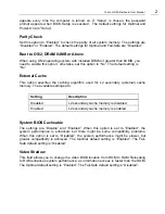
Page 17: ...caching algorithm used for L2 secondary external cache memory The available settings are Setting Description Disabled L2 secondary cache memory is disabled Enabled L2 secondary cache memory is enabled System BIOS Cacheable The settings are Disable and Enabled When this option is set to Enabled the system performance is enhanced but there might be some compatibility problems When this option is set...

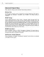
Page 18: ...nual you can modify the options from DRAM Refresh Rate to Turn Around Insertion and will affect the system performance and its stability The recommendation for user is to change only the speed of both the DRAM Refresh Rate and the ISA Clock Divisor so that the speed is the same as the CPU Bus Clock If the system becomes unstable we recommend the user to choose the 70ns option DRAM Parity Check Cho...

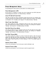
Page 19: ...f display inactivity has expired The settings are Disabled Standby and Suspend The default setting is Standby Hard Disk Power Down Mode This option specifies the power management state that the hard disk drive enters after the specified period of display inactivity has expired The settings are Disabled Standby and Suspend The default setting is Suspend Hard Disk Timeout Min This option specifies t...

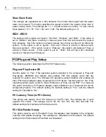
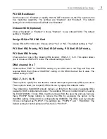
Page 20: ...ng section describes the PCI PnP Setup menu Plug and Play Aware OS Set this option to Yes if the operating system installed in the computer is Plug and Play aware AMIBIOS only detects and enables PnP ISA adapter cards that are required for system boot The Windows 95 operating system detects and enables all other PnP aware adapter cards Windows 95 is PnP aware Set this option to No if the operating...

Page 21: ...g is Auto DMA channel 0 to 7 Choose either PNP or ISA EISA setting If your ISA card is not Plug and Play and requires DMA then choose ISA EISA setting on the DMA channel that it uses The default setting is PNP IRQ3 7 9 11 14 15 These options specify the bus that the named interrupt request lines IRQs are used These options allow you to specify IRQs for use by legacy ISA adapter cards They determin...

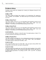
Page 22: ... 2F8h 2E8h 3F8h 3E8h Auto and Disabled The Optimal and Fail Safe default settings are both Auto Serial Port2 Mode You can choose either Normal or other IR modes The default setting is Normal The IR mode should be set according to your IR device OnBoard Parallel Port This option enables the parallel port on the motherboard and specifies the parallel port base I O port address The settings are 378h ...

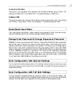
Page 23: ...system can be configured so that all users must enter a password every time the system boots or when the BIOS Setup is executed The password is stored in CMOS RAM When you select Supervisor or User AMIBIOS prompts for a password You must set the Supervisor password before you can set the User password Enter a 1 6 character password The password does not appear on the screen when typed Make sure yo...

Page 24: ...You can also press the F10 key anywhere in the BIOS Setup program main menu to do this Exit Without Saving Exits the Setup program without saving any changes This means that any changes made while in the Setup program are discarded and NOT SAVED Pressing the ESC key in BIOS Setup program main menu will do this ...

Page 25: ...NG The procedures in this chapter assume familiarity with the general terminology associated with personal computers and with the safety practices and regulatory compliance required for using and modifying electronic equipment Disconnect the system from its power source and from any telecommunications links networks or modems before doing any of the procedures described in this chapter Failure to ...

Page 26: ...em password you can clear the password by moving a jumper The system has been properly configured at the factory Normally the only time you will ever change a jumper is if you need to Change the system operating speed Clear the User or Administrator password Reset the CMOS RAM settings to the default values Figure 2 shows the location of the jumper blocks on the system board Descriptions of how to...

Page 27: ...Yukon HX Motherboard User Manual 3 Figure 2 Jumper Block Locations ...

Page 28: ...s should be changed only when you upgrade the CPU CPU BUS Spees Clock Ratio Jumpers CPU SPEED J2 J3 J4 J5 JB1 PENTIUM 75 MHz 1 2 3 ON ON OFF 1 2 3 4 5 6 PENTIUM 90 MHz 1 2 3 ON OFF ON 1 2 3 4 5 6 PENTIUM 100 MHz 1 2 3 OFF ON ON 1 2 3 4 5 6 PENTIUM 120 MHz 1 2 3 ON OFF ON 1 2 3 4 5 6 PENTIUM 133 MHz 1 2 3 OFF ON ON 1 2 3 4 5 6 PENTIUM 150 MHz 1 2 3 ON OFF ON 1 2 3 4 5 6 ...

Page 29: ...M 233 MHz 1 2 3 OFF ON ON 1 2 3 4 5 6 How to Clear CMOS Contents J8 This procedure should be done after the system BIOS is updated 1 Power off the computer and remove the system cover 2 You can clear the system CMOS by shorting pins 1 2 for a brief moment To do so place the jumper cap on the J8 pins 1 2 3 Power on and allow the system to boot 4 Power off ...

Page 30: ...from the J8 pins 1 2 6 Replace the system cover and turn the power back on BIOS Mode Select Jumpers J11 This section tells how to select BIOS mode by using jumper J11 Mode allows updates of PnP configuration into NVRAM J11 Non Plug Play 2 3 Plug Play 1 2 Default BIOS mode setting ...

Page 31: ...r the RESET switch is pushed and released by user CPU Fan 12V CPU fan connector EXTSMI SW This allows the user to manually place the system into a suspend mode or Green mode where system activity will be instantly decreased to save electricity and expand the life of certain components when the system is not in use This 2 pin connector connects to the case mounted suspend switch EXTSMI is activated...

Page 32: ...and workstations for optimal utilization of the 133 MB sec PCI local bus The onboard SCSI is tested extensively over a large matrix of operating systems peripherals and systems to ensure a high degree of compatability and reliability The PCI host interface on the SCSI supports the 32 bit PCI interface with the bus master burst data transfer up to the maximum rate of 133 MB sec Data is parity prote...

Page 33: ...er and start Windows 95 2 Windows 95 will automatically detect any new hardware A New Hardware Found screen appears once it detects the Adaptec AIC 7860 PCI to UltraSCSI Controller Chip Your system will locate and install the built in Adaptec 7860 SCSI driver automatically 3 To finish setting up your new hardware you must restart your computer If your computer does not automatically install the SC...

Page 34: ...g and Configuring Motherboard Options 3 30 3 Click on the Properties button Select Driver sheet and then click on Change Driver 4 A Select Hardware Type screen pops up Highlight SCSI controller and then click OK ...

Page 35: ...stall Adaptec 7860 SCSI driver If you have the Power CD ver 2 0 the path for the Adaptec 7860 SCSI driver is D mthrbrds yukonhx scsi7800 win95 aic78xx inf where D is your CD ROM drive Once the file aic78xx inf is highlighted click OK Click OK again to accept the driver ...

Page 36: ... Device screen pops up Click on OK and a PCI SCSI Bus Controller Properties screen appears Click OK again to acknowledge 7 Finally a System Settings Change screen appears Choose Yes to restart the computer and the driver installation will take effect after restart ...

Page 37: ...CSI cable There is also an optional External SCSI cable available for users Figure 3 Standard Internal SCSI cable Color Strip The Internal SCSI cable is a fifty pin flat ribbon cable with three internal device connectors To connect the SCSI cable plug the end of the cable into the J28 SCSI connector on the motherboard host connector The colored stripe on one side of the ribbon cable must match wit...

Page 38: ...e external SCSI cable should be connected for internal and or external SCSI devices If there is NO external SCSI device attached such as Device 1 and Device 2 then a active terminator is required to be in place at the external port connector SCSI ID Number All SCSI device including this board have a SCSI identification number that is not in used by any other SCSI device There are eight possible ID...

Page 39: ...chase a 3 3V voltage regulator from any electronic store Once you purchase the 3 pin 3 3V voltage regulator cut the pin so that the remaining length of the pin is approximately 0 25 inch Approval 3 3 Voltage Regulator List Vendor Part Code Linear Tech LT1083 7 5 AMP LT1084 5 AMP LT1085 3 AMP Low Dropout Positive Adjustable Regulators Alpha AS2830 3 AMP AS2840 4 AMP AS2850 5 AMP AS2880 8 AMP Adjust...

Page 40: ...ector J31 JP9 Once the 3 3V voltage connector be installed on the board JP9 and J31 needed to be opened leave the jumper caps off for P55 upgrade CPU VOLTAGE JP9 J31 3 3 3 6V P54C 1 3 5 7 9 11 2 4 6 8 10 12 All ON ON 2 8 2 9V P55 1 3 5 7 9 11 2 4 6 8 10 12 All OFF OFF ...

Page 41: ...r to the PCI slots Installing the Optional USB PS2 add on card The female connector at the bottom end of this card plugs onto JP6 on the Yukon HX motherboard located between the COM1 and COM2 headers The USB connectors and PS2 connector must face toward the outside of the computer case NOTE Your System BIOS may need to be Upgraded to support your new USB PS2 add on card features This can be obtain...

Page 42: ...an 8 MB SIMM in the second socket of bank 0 You may however use different size SIMMs between banks When adding SIMMs use only tin lead 72 pin 70 ns fast page SIMMs or for optimum performance 60 ns EDO DRAM Either ECC parity or non parity SIMMs are supported The types of SIMMs that can be installed are listed in Table 1 Table 2 lists the possible combinations of SIMM types and the resulting amount ...

Page 43: ...8 MB 32 MB 64 MB total in bank 1 32 MB 64 MB total in bank 0 To install SIMMs do the following procedure 1 Holding the SIMM only by the edges remove it from its antistatic package 2 Position the SIMM at about a 45 angle relative to the system board Make sure the small notch in the middle of the bottom edge of the SIMM aligns with the notch in the SIMM socket 3 Insert the bottom edge of the SIMM in...

Page 44: ...m 3 Turn off the system 4 To gain access to the SIMM sockets remove the system cover 5 Gently spread the retaining clip at each end of the SIMM just enough to allow you to rotate the top edge of the SIMM downward to an angle of about 45 6 Holding the SIMM only by the edges lift it away from the socket and store it in an antistatic package 7 Reinstall and reconnect any parts you removed or disconne...

Page 45: ...t Operational A memory failure in the first 64 KB of memory or Timer 1 on the motherboard is not functioning 5 Processor Error The CPU generated an error 6 8042 Gate A20 Failure The BIOS cannot switch to protected mode 7 Processor Exception Interrupt Error The CPU on the CPU card generated an exception interrupt 8 Display Memory Read Write Error The system video adapter is either missing or its me...

Page 46: ...d by a battery The battery power is low Replace the battery CMOS Checksum Failure CMOS RAM checksum is different than the previous value Run BIOS Setup CMOS System Options Not Set The values stored in CMOS RAM have been destroyed Run BIOS Setup CMOS Display Type Mismatch The video type in CMOS RAM does not match the type detected Run BIOS Setup CMOS Memory Size Mismatch The amount of memory found ...

Page 47: ... Interrupt channel 2 failed POST Invalid Boot Diskette The BIOS can read the disk in floppy drive A but cannot boot the system with it Use another boot disk and follow the screen instructions Keyboard is Locked Unlock It The keyboard lock on the system is engaged The system must be unlocked to continue to boot Keyboard Error The keyboard has a timing problem Make sure a Keyboard Controller AMIBIOS...

Page 48: ...or Parity error in motherboard memory The format is ON BOARD PARITY ERROR ADDR XXXX XXXX is the hex address where the error occurred Run AMIDiag to find and correct memory problems Parity Error Parity error in system memory at an unknown address Run AMIDiag to find and correct memory problems ...

Page 49: ...e damage to the motherboard Reflash BIOS 1 Insert the BIOS diskette into your floppy drive At A type amiflash BIOS filename and hit enter 2 A Flash EPROM Programming Utility screen pops up Make sure the version of the AMIFLASH BIOS is 5 23 or above Press Y to continue WARNING System must NOT be turned off during the Programming operation System will Re Boot if Programming is successfully complete ...

Reviews: