background image

PROBLEM

PROBABLE  CAUSES

Try…

Blank Display

Faulty wiring from power source to 

meter or faulty AC power supply

Check for miswiring. Measure voltage with DMM 

where red and black wires connect to terminal 

block TB2 inside meter display head.  Verify cor-

rect polarity and confirm that voltage is steady and 

between 9Vdc and 32Vdc

Flow rate reads zero continuously 

regardless of flow 

Flow is below cutoff

Increase flow above cutoff

Flow rate shows [-] negative flow  

and FWD total remains at [0] zero, 

when flow is greater than cutoff

Meter is installed backwards 

Reinstall correctly

Flow rate reading fluctuates ex-

cessively when flow is unchang-

ing

Excessively turbulent or unsteady 

flow due to partially closed valves 

or other flow obstructions

Pipe not full.

Pulsing flow due to combining mul-

tiple upstream flow sources

Insufficient mixing of upstream 

chemicals

Low fluid conductivity < 20 µS/cm

Noisy electrical environment

Defective or noisy ac switching 

power supply

Eliminate or minimize causes of flow disturbances 

or increase meter damping 

Provide back pressure or other means to ensure 

pipe is filled

Move connection point further upstream

Move chemical injection downstream from meter

Replace with different type of meter

Improve grounding at meter and nearby potential 

ly noisy electrical equipment. Increase distance 

between meter and electrical noise sources. 

Replace power supply

Flow Rate appears correct but 

pulse/ frequency output is low, 

erratic or absent

Wiring incorrect

External device input impedance 

too low

Cable too long

Compare wiring with appropriate wiring recom-

mendations

Use sourcing rather than sinking interface connec-

tion

Reduce interface pull-up resistance

Flow Rate appears correct but 

pulse/frequency output is erratic 

and/or too high

Electrical noise sources interfering 

with pulse frequency signal

Wrong type of cable

Grounding problem

Isolate, remove or reduce noise sources. Move 

meter control cable away from noise sources. 

Use only twisted pair cable and ensure both signal 

wires are on same twisted pair

Improve or try different grounding method.

Flow rate reads “COMM FAIL” 

instead of rate

Cable between flow sensor body 

and display head  is disconnected, 

miswired or damaged

Inspect cable for damage. Check cable connection 

inside display head for correct wiring to five-posi-

tion connector, ensure that connector is properly 

inserted, inspect for broken connections. 

Page 17

NOTES

Summary of Contents for iMAG

Page 1: ...9 0 0 1 2 0 0 8 CERTIFIED COMPANY ISO 9 0 0 1 2 0 0 8 CERTIFIED COMPANY ISO PROUDLY MADE IN THE USA Flow Meters Controls Municipal Industrial Magmeter Instructions iMAG...

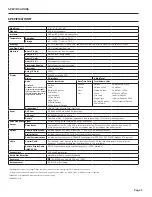
Page 2: ...tallation Page10 External Power and Wiring Page11 Battery Power Pulse Output Analog Output Hart Communication Page12 Digital Output Serial Communication Cable Control Wiring K Factors for High Speed D...

Page 3: ...andard Rate and total units and pulse output are settable via the front panel touch key pad by the user Bi directional flow is standard Forward reverse and net flow can be read from the display If for...

Page 4: ...s drilled screws 2 for tamper evidence iMAG 4600 0400 Welded steel epoxy coated flow tube Flanges 150 lb ANSI pattern Santoprene Polypropylene Liner Equalization lug Powder coated ductile cast iron el...

Page 5: ...llons Second Minute Hour Day Gallons Gallons x 1000 Million Gallons Liters Kilo Liters Mega Liters Barrels 42 gallon Cubic Meters Cubic Meters x 1000 Cubic Feet Cubic Feet x 1000 Million Cubic Feet Im...

Page 6: ...ONS Cable Exit Cable Exit iMAG4600 0300 Shown L H T Including Rubber Gaskets Metal Flange ID iMAG4600 0400 to 1200 Shown Cable Exit iMAG3600 Remote Shown L T Including Rubber Gaskets Metal Flange ID 3...

Page 7: ...ICATIONS iMAG Accuracy Accuracy m s 0 1 2 3 4 5 33 0 5 10 15 20 25 30 ft s 0 1 2 3 4 5 5 10 15 20 25 30 33 0 4 2 0 6 8 10 Flow Velocity iMAG Dimensions iMAG Meter Size L H T ID Shipping Weight inch mm...

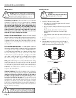
Page 8: ...libration The iMAG is factory calibrated and will not require any form of field calibration Caution These flow sensors are not recommended where installation may expose the flow sensor to boiler press...

Page 9: ...flange plate For the best electrical bonding remove rust and paint to expose clean bare metal where the equalization flange plate lock washer contacts the pipe flange Connection must be inspected per...

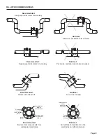
Page 10: ...MMENDATIONS 1X 2X 2X 2X 1X 5X 5X 5X Reduced Pipe Two Elbows In Plane Two Elbows Out Of Plane Expanded Pipe Swirling Flow Propeller Meter Partially Open Butterfly Valve 1X 1X 1X 1X Swirling Flow iMAG i...

Page 11: ...Intermittent air bubbles pass over electrode Possible sediment build up iMAG iMAG iMAG iMAG Recommended Allows air to bleed off Recommended Keep pipe full at meter for accuracy Recommended Keeps pipe...

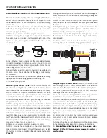
Page 12: ...ug and discard 5 After removing the cable gland bulkhead nut insert the plug and cable gland bushing through the open hole Install the nut back onto the cable gland threads inside the housing and tigh...

Page 13: ...ctions of the other wiring options such as Pulse Output P Analog Output L Digital Output D or Serial Output SS The fourth character X is reserved for future applications Application wiring and other e...

Page 14: ...resistor RL will be needed to convert the loop current to voltage for voltage only input devices The meter s loop transmitter minimum voltage drop is 6Vdc 8Vdc with HART which with wiring resistance a...

Page 15: ...plication diagrams on page 12 for recommended connections to external equipment These outputs are electrically similiar to the Pulse Output described above except they are capable of output frequencie...

Page 16: ...cation Sinking Mode Recommended for Rin 30k Orange Blue Power Source Vs 6 36Vdc RL _ 4 20mA Current Output Analog Output _ _ _ Loop Meter Cable User Equipment Analog 4 20mA Current Loop Output Applica...

Page 17: ...ence to return to the HOME screen you tap four times You will be redirected to a SUBMENU screen which pro vides access to more information about the meter such as serial numbers firmware revisions Mod...

Page 18: ...illed Move connection point further upstream Move chemical injection downstream from meter Replace with different type of meter Improve grounding at meter and nearby potential ly noisy electrical equi...

Page 19: ...Page 17 NOTES...

Page 20: ...LT 103199r1 5 20161101 11 1 16 Seametrics Incorporated 19026 72nd Avenue South Kent Washington 98032 USA P 253 872 0284 F 253 872 0285 1 800 975 8153 www seametrics com...

Reviews: