


Page 13
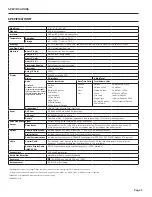
INPUTS/OUTPUTS and OPERATION
Power
Source
Options
Installed
OID
Codes
Cable Conductor Usage
Red
Black
Green
White
Orange
Blue
AC
One Pulse, HART
APHX
Do Not Connect
Do Not Connect
Pulse +
Pulse -
4-20mA Out +
4-20mA Out -
DC
One Pulse, HART
DPHX
DC PWR +
DC PWR -
Pulse +
Pulse -
4-20mA Out +
4-20mA Out -
DC
One Pulse, 4-20mA Output
DPLX
DC PWR +
DC PWR -
Pulse +
Pulse -
4-20mA Out +
4-20mA Out -
DC
Two Digital Outputs
DDDX
DC PWR +
DC PWR -
Out 1 +
Out 1 -
Out 2 +
Out 2 -
DC
4-20mA Output 1 Digital Output
DDLX
DC PWR +
DC PWR -
Out 1 +
Out 1 -
4-20mA Out +
4-20mA Out -
DC
RS-485 Serial Comm
DSSX
DC PWR +
DC PWR -
RTS
Signal Ground
B
A
DC
One Pulse Output
DPXX
DC PWR +
DC PWR -
Pulse +
Pulse -
Do Not Connect
Do Not Connect
AC
One Pulse, 4-20mA Output
APLX
Do Not Connect
Do Not Connect
Pulse +
Pulse -
4-20mA Out +
4-20mA Out -
AC
Two Digital Outputs
ADDX
Do Not Connect
Do Not Connect
Out 1 +
Out 1 -
Out 2 +
Out 2 -
AC
4-20mA Output 1 Digital Output
ADLX
Do Not Connect
Do Not Connect
Out 1 +
Out 1 -
4-20mA Out +
4-20mA Out -
AC
RS-485 Serial Comm
ASSX
Do Not Connect
Do Not Connect
RTS
Signal Ground
B
A
AC
One Pulse Output
APXX
Do Not Connect
Do Not Connect
Pulse +
Pulse -
Do Not Connect
Do Not Connect
Battery
One Pulse Output
BPXX
Do Not Connect
Do Not Connect
Pulse +
Pulse -
Do Not Connect
Do Not Connect
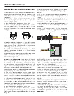
Control Cable Wiring
Digital Output Connection.
When the second or third OID code
character is “D”, refer to “
Digital Output Application”
diagrams on
page 12 for recommended connections to external equipment.
These outputs are electrically similiar to the Pulse Output described
above except they are capable of output frequencies up to 10kHz.
Frequency output scaling is user-settable via the FOUT tab on the
meter’s setup menus. Selections are: 500Hz and 1, 2, 5 and 10
KHz at maximum flow rate.
Serial Communication Connection.
When the second and third
OID code characters are “SS”, refer to
“Control Cable Wiring”
table
below for recommended connections to external equipment. These
connections provide a half-duplex, isolated, RS485 serial
communications port using the Modbus messaging protocol.
The port is reconfigurable by internal jumper settings to
full-duplex RS232 or 3.3V CMOS. The TXD connection
is the transmitted data output from the meter and RXD
is the received data input to the meter. See Seametric’s
Modbus Interface Description, LT-103393 (available at www.
seametrics.com) for supported Modbus message protocol
and electrical interface specifications.
Cable Shield.
In general, the cable shield and its bare drain
wire should be left unconnected at the user equipment end
of the cable to minimize “ground loop” problems.
FOUT (Hz)
Size
500
1K
2K
5K
10K
3”
41.55125
83.10249
166.205
415.5125
831.0249
4”
23.3463
46.69261
93.38521
233.463
466.9261
6”
10.37703
20.75406
41.50813
103.7703
207.5406
8”
5.836576
11.67315
23.3463
58.36576
116.7315
10”
3.735525
7.47105
14.9421
37.35525
74.7105
12”
2.594034
5.188067
10.37613
25.94034
51.88067
K-factors for High Speed Digital Output (High Frequency)
Summary of Contents for iMAG
Page 19: ...Page 17 NOTES...


