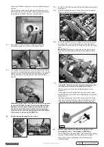
4.6.9 Remove VS4984 Holding Tool from the camshaft gear and
slowly turn the camshafts to position the ‘timing flats’ to
achieve the correct alignment to the Setting Plate. This will
allow the Camshaft Setting Plate to be bolted down, using the
securing bolts provided, in order that the Plate
rests fully
on
the surface of the cylinder head (fig.27).
WARNING: The camshaft ‘timing flats’ MUST BE in correct
alignment to the Setting Plates BEFORE the securing
screws of the Setting Plates are tightened down. The action
of tightening the securing screws of the Setting Plates
MUST NOT be used to turn the camshaft to position the
‘timing flats’ alignment, as damage to the cylinder head will
result.
4.6.10 Repeat this procedure on the other bank of camshafts.
NOTE:
Discard the old camshaft gear bolts – always fit new
camshaft gear bolts.
WARNING: Tightening procedure for camshaft gear bolts:-
For early engines, Jaguar instructs that the EXHAUST
camshaft gear bolt is tightened first, followed by the INLET
gear bolt.
However, for later engines Jaguar and Land Rover instruct
that the INLET camshaft gear bolts MUST BE tightened
before the EXHAUST gear bolts, and a WARNING is given
that failure to tighten the INLET camshaft gear bolts first,
will result in engine damage.
4.6.11 Fit new bolts and use VS4984 Holding Tool to counter-hold the
exhaust camshaft gear. Tighten the new camshaft gear bolts to
specified torque (fig.28).
4.7
Removal of timing chains and gears.
Primary chains
4.7.1 Follow the procedure for “Checking valve timing”, and fit the
appropriate Flywheel Locking Pin and the Camshaft Setting
Plates on both banks of camshafts.
4.7.2 Remove the crankshaft pulley following the procedure detailed
earlier.
4.7.3 Remove the front timing chain cover and the VVT control
solenoid housing, if fitted.
4.7.4 Commence work on the left-hand bank first as the primary chain
from this bank is at the front of the crankshaft gear and therefore
must be removed first to allow access to remove the other
primary chain.
fig.27
fig.28
NOTE:
In order for the camshaft timing to be correct,
both
VS4983 Setting Plates
MUST fit flush on to the ‘timing flats’
and rest fully on the surface of the cylinder head.
4.6.5 To adjust the position of the camshafts to achieve this position
the inlet and exhaust camshaft gear bolts must be slackened.
Work on one bank of camshafts at a time.
4.6.6 Install an VS4983 Camshaft Setting Plate loosely across the
‘timing flats’ on the camshafts.
DO NOT
tighten the securing
bolts of the Setting Plate at this stage (fig.24).
VS4984 Camshaft Gear Holding Tool
4.6.7 Fit VS4984 Camshaft Gear Holding Tool in to the holes in the
EXHAUST camshaft gear and use it to counter-hold whist
slackening the
INLET
camshaft gear bolt (fig.25).
4.6.8 Maintain VS4984 Holding Tool in this counter-holding position
and slacken the
EXHAUST
camshaft gear bolt (fig.26).
NOTE:
It may be necessary to fit a breaker bar into the square
drive provided in VS4984 Tool, to increase its counter-holding
leverage.
fig.24
fig.25
fig.26
Original Language Version
© Jack Sealey Limited
VS4980
Issue No: 3 (SP) 08/07/15


