


5. OPERATION
WARNING!
Ensure that you have read, understood and applied Section 1 Safety Instructions.
5.1.
Make sure that the main switch (fig.3) is ‘Off’ (up).
5.2.
Ensure that the tank drain valve is closed. (See fig.4).
5.3.
Close the outlet pressure regulator by turning the knob clockwise (See fig.2).
5.4.
Connect the air tool required to the compressor via an air line connected to the air outlet (See fig.2).
5.5.
Plug the mains cable into the mains supply and start the compressor by setting the Auto-On /Off to the Auto-On position i.e. horizontal.
5.6.
Allow the pressure in the tank to rise to the maximum at which point the compressor will automatically cut out. Tank pressure is shown
on the larger gauge (fig.2).
5.7.
Begin to gradually open the regulator by turning the knob anticlockwise until the small gauge registers the required operating pressure
specified for the tool to be used. Always adjust up to the required pressure rather than down from a higher pressure. The required
setting, once achieved, can be locked by screwing the locking ring (See fig.2) up tight underneath the adjusting knob.
5.8.
You can now begin to use the tool. The compressor will operate automatically cutting in and out as required to restore the air pressure
in the tank. The pressure switch (fig.2) stops the motor when the maximum tank pressure is reached and restarts it when pressure
falls below the minimum threshold - approx. 2 bar (29psi) less than the maximum pressure.
NOTE:
a) If the motor does not cut in and out, but runs continuously when using an air appliance, the capacity of the compressor may
be too small for the appliance.
b) The main gauge (fig.2) indicates the pressure inside the main tank, NOT the pressure supplied to the air equipment, which is shown
on the smaller gauge (fig.2). Should the pressure in the main tank exceed the pre-set switch (fig.2) maximum, the pressure relief valve
(fig.3) will activate.
fig.5
S
AC0607S, SAC2410S, SAC5016S Issue 1 09/03/21
Original Language Version
© Jack Sealey Limited
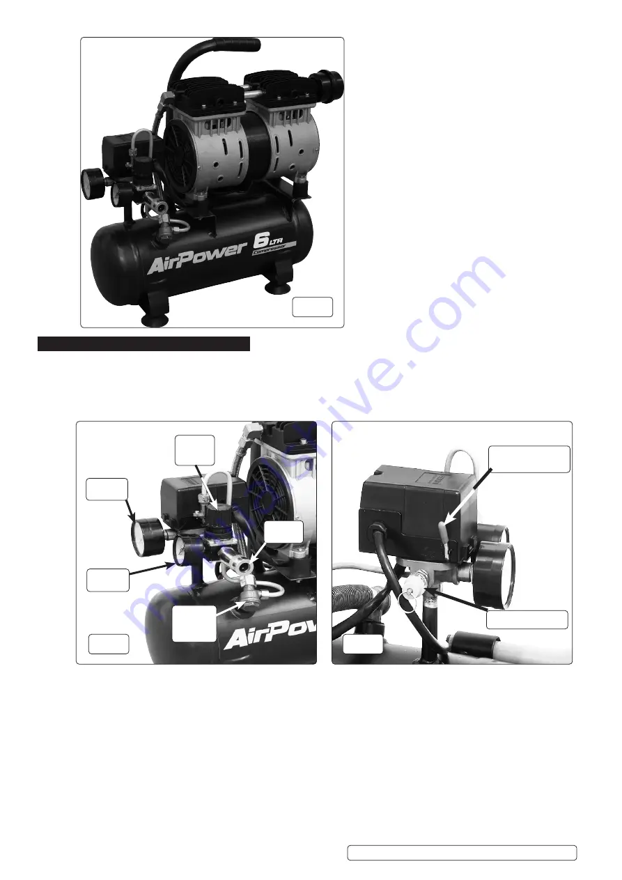
Pressure
gauge
Output
gauge
Air
Outlet
Pressure
Regulator
Tap
Non
Return
Valve
A
uto-On / Off Lever
(up is OFF)
Pressure Relief
Valve
fig.3
fig.2
fig.1


