background image

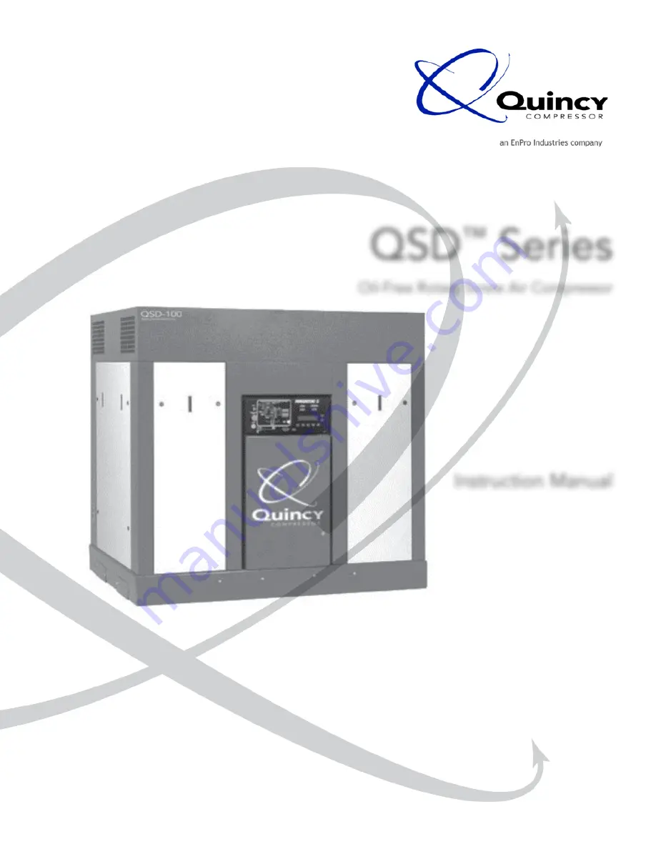
QSD

 Series 

Oil-Free Rotary Screw Air Compressor

Instruction Manual

This manual contains important safety information and should be made available to 

all personnel who operate and/or maintain this product. Carefully read this manual 

before attempting to operate or perform maintenance on this equipment.

Manual No. 65040-AB

January 2001 Edition

Summary of Contents for QSD 65040-AB

Page 1: ...s manual contains important safety information and should be made available to all personnel who operate and or maintain this product Carefully read this manual before attempting to operate or perform...

Page 2: ......

Page 3: ...re Separator 10 Capacity Control System 11 12 Electrical System 12 14 Indicators 14 15 Section III Installation Receiving 16 Moving the Unit to the Installation Site 16 Location 16 17 Piping Connectio...

Page 4: ...to Power ync II version 1 04 32 Back up Mode Operation 32 33 Single Machine Operational Mode 33 Multiple Machine Operational Mode 33 34 Pressure Settings 34 35 Network Installation 35 37 Network Volta...

Page 5: ...ves to be defective If requested by Seller such product or part thereof must be promptly returned to Seller freight collect for inspection Seller warrants factory repaired or replaced parts of its own...

Page 6: ...4 Quincy Compressor QSD DIMENSIONAL DATA air cooled D E L O O C R I A D S Q A T A D T H G I E W P H T H G I E W S B L 0 5 0 0 3 4 5 7 0 0 1...

Page 7: ...Quincy Compressor QSD 5 DIMENSIONAL DATA water cooled D E L O O C R E T A W D S Q A T A D T H G I E W P H T H G I E W S B L 0 5 0 0 5 4 5 7 0 5 7 4 0 0 1 0 0 0 5...

Page 8: ...ction of the pressure relief valve or replace the pressure relief valve with a plug Over pressurization of system or compressor components can occur resulting in death severe personal injury or proper...

Page 9: ...ORIGINAL START UP must be made in all communication relative to parts orders or warranty claim A model serial number plate is located on the frame OR IN the upper right corner of the control panel doo...

Page 10: ...Section II Description 8 Quincy Compressor QSD MODEL IDENTIFICATION...

Page 11: ...to the discharge of stage two Each stage consists of two rotors in constant mesh housed in a cylinder with two parallel adjoining bores Each male rotor has lobes that mesh with flutes in the female r...

Page 12: ...discharge temperature The air then passes through a moisture separator trap then into stage two of the compressor The stage two cooler cools the water glycol 70 30 mixture which is circulated through...

Page 13: ...y to compress air This vacuum creates a reverse pressure differential across the bearing seals causing the bearing fluid to migrate toward the compression chamber when the machine is unloaded The QSD...

Page 14: ...Continuous Run Mode a properly sized air receiver will ensure that the compressor operates and reacts properly as air system demand changes NOTE Refer to section VIII for Power ync II operating instr...

Page 15: ...one of the following conditions occurs at any time the unit will immediately shutdown The unit should not be restarted until the problem has been corrected The fluid pressure does not reach 15 PSI wi...

Page 16: ...ypass or tamper with any safety HAT switch or sensor Failure to provide this safety feature could cause death serious injury and property damage If the compressor is shutting down due to high discharg...

Page 17: ...e control panel in Back up Mode Low Lube Light This indicator signals that the compressor has shutdown due to low fluid pressure NOTE There is no indication of low fluid pressure on the control panel...

Page 18: ...d to move the unit to its installation site use forklift slots provided in the side or end of the main frame Use of chains and slings should be limited to the main frame Do not attempt to lift the uni...

Page 19: ...t the unit to the floor to prevent the accidental breakage of piping or electrical connections as a result of being bumped Use only lag bolts to secure the unit Do not pull the bolts down tight as thi...

Page 20: ...shut off valve if the purpose is to isolate the compressor from a system for servicing If a manual shut off valve is installed at the service connection it must be open to allow air to pass to the se...

Page 21: ...enclosures and components must be appropriate to the area in which they are installed Pneumatic Circuit Breakers or Velocity Fuses The Occupational Safety and Health Act Section 1926 303 Paragraph 7 p...

Page 22: ...tested regularly especially when using an open cooling tower Contact the factory if you plan to use a water glycol coolant salt or brackish water Table 3 2 Water Quality M E T I E C N O H G U O R H T...

Page 23: ...ower input end The power input end of the compressor is marked with an arrow located on the motor adapter noting the proper rotation To check for proper rotation briefly jog the start button allowing...

Page 24: ...e enclosure Check inlet and discharge water piping for proper connections adequate supply and open drain CAUTION NOTE When freezing temperatures are expected before the next start up drain all cooling...

Page 25: ...E G A T S G I S P 8 3 7 2 G I S P 4 2 G I S P 0 5 E R U S S E R P E G R A H C S I D O W T E G A T S G I S P 1 3 1 0 6 G I S P 2 0 2 1 D A O L N U X A M G I S P E R U S S E R P D I U L F G I S P 8 2 8...

Page 26: ...ystem to prevent any back up of air flow into the area to be serviced Never depend upon a check valve to isolate the system 3 Open the manual vent valve and wait for the pressure in the system to be c...

Page 27: ...Section V Preparing for Maintenance or Service Quincy Compressor QSD 25 THIS PAGE INTENTIONALLY LEFT BLANK...

Page 28: ...instructions Unusual noise or vibration indicates a problem Do not operate the compressor until the source has been identified and corrected Fluid Specifications Each QSD unit comes equipped with a fl...

Page 29: ...the off position and locked out to assure that the compressor will not start automatically or by accident Close unit shut off valve to eliminate buffing air venting Fluid Filter The fluid filter is a...

Page 30: ...r lip of the fluid slinger and pop the slinger from the seal adapter bore b Using a brass drift tap the shaft seal assembly from the seal bore c Inspect both seal lips for excessive wear lip flaws or...

Page 31: ...ng air flow 2 A sinuous seal with an air dam 3 An atmospheric fluid drain on the bearing side The sealing system incorporates a redundant seal system to ensure no fluid enters the compressor chamber T...

Page 32: ...ting Pressure Switch The following procedure should be used for maximum safety when preparing for maintenance or service 1 Disconnect and lockout the main power switch and hang a sign at the switch of...

Page 33: ...Section VII Service Adjustments Quincy Compressor QSD 31 THIS PAGE INTENTIONALLY LEFT BLANK...

Page 34: ...harge of each compressor stage at the inlet of stage two and at the discharge of the package There is a coolant flow switch to prevent the unit from running if there is no coolant flow If the unit is...

Page 35: ...g this waiting period the control will turn the compressor motor s off and will stand by continuing to monitor system pressure When a demand returns to the system the controller will restart the compr...

Page 36: ...pressure remains steady throughout a typical work cycle the differential can be reduced to as low as 5 PSIG If the system pressure fluctuates greatly at 15 PSIG indicating little system storage capac...

Page 37: ...1 02 or 03 communications cable 2 One cable terminator box Quincy part number 140715 3 Conduit is required for NEMA 4 applications and strongly recommended for all other applications The maximum total...

Page 38: ...etwork it will be run to the terminator box 13 After the two cables have been stripped to expose 3 8 of bare wire tightly twist the blue wire from each cable together Next twist the white wires togeth...

Page 39: ...the full capacity of selected compressors these compressors may be networked together There are nine positions available for machines in a network see Compressor Settings and Maintenance Displays page...

Page 40: ...program also checks the function of the LCD display screen If the controller cannot properly communicate with the display it will flash all the amber warning lights to draw attention to this fact If t...

Page 41: ...ompressor and check the connection at the temperature probe and the controller If a loose connection is found correct the problem and repeat the start up procedure If all connections are tight the pro...

Page 42: ...d then reapplied without having corrected the fault one of the following displays will be visible NOTICE A CONTROL RELAY IS NOT DISENGAGED REFER TO YOUR SERVICE MANUAL OR CONTACT YOUR SERVICE REPRESEN...

Page 43: ...e Power ync II computer to operate the compressor if it cannot find the correct checksum number in the setup information Operation using the default checksum may not be as efficient as operation would...

Page 44: ...possible If the element has been recently changed and does not appear to be clogged a likely cause of these displays is a loose connection at either the switch or the controller NOTICE A FILTER NEEDS...

Page 45: ...s for STAGE 1 OUT STAGE 2 OUT and the FLUID PRESSURE These pressures provide verification of the normal operation of the compressor Operational Displays When START is pressed one of three displays sho...

Page 46: ..._ RUNNING IN CONTINUOUS RUN MODE PRESS ENTER KEY TO SELECT MENU HOURS______STG 2 OUT TEMP______ Continuous Run Mode is the second primary operational Mode and is identical to Auto Dual Mode except the...

Page 47: ...splay does not make reference to ENTER pressing ENTER will take the operator back to the previous display From the initial Start up Display or any of the Operational Displays pressing ENTER will call...

Page 48: ...ration Menu to select the Continuous Run Configuration Under this mode of operation the compressor will load and unload as system demands are met but will not time out and shutdown the main motor CONT...

Page 49: ...TWORK CONFIGURATION IN PROGRESS This message will be briefly displayed as the controller communicates its ID and operational capabilities to the other compressors on the network The display will then...

Page 50: ...slower rate This indicates that changes can be made to that particular position number Use the UP or DOWN arrow keys to select the machine ID Once the proper machine ID has been selected press ENTER t...

Page 51: ...the UP or DOWN arrow keys to scroll through the sequence numbers As the numbers scroll the actual compressor sequence will be displayed in the area to the right of SEQ When the desired sequence is di...

Page 52: ...onfiguration Menu 4 From this display sequences and schedules can be cleared from all on line networked compressors at one time from one machine NETWORK CONFIGURATION MENU 4 CLEAR SEQUENCE PRESS F1 CL...

Page 53: ...ss ENTER to return to the previous display LOADED HOURS _____ UNLOADED HOURS _____ HOURS SINCE LAST FLUID CHANGE _____ PRESS ENTER TO RETURN This display shows the number of hours that the compressor...

Page 54: ...reset PRESS F1 TO RESET FLUID HOURS PRESS ENTER TO RETURN If this is the correct hourmeter to reset press F1 again If this is not the hourmeter that needs to be reset press ENTER to return to the pre...

Page 55: ...e control will briefly display a message that it is transferring the new time setting to all on line compressors There is no need to reset each compressor in a network The control will automatically s...

Page 56: ..._____ LOAD PRESS _______ UNLOAD PRESS ______ FLUID PRESS ______ MACHINE ID __________ This display shows the HAT shutdown STAGE 2 setting interstage shutdown pressure setting maximum unloaded pressure...

Page 57: ...MODEM BAUD RATE PRESS F1 COMPRESSOR DIAGNOSTIC MENU PRESS F2 UP FOR NEXT MENU DOWN FOR PREVIOUS MENU Press F1 to set the modem baud rate Changes to the modem baud rate setting should only be made if t...

Page 58: ...is not plugged into a 115 volt outlet ERRORS is the number of various errors detected from other machines in the network Each time information is sent out on the network the control looks for an ackno...

Page 59: ...to the right 09 Trim control for the network has passed to the right The example shown indicates that the A machine is running fully loaded and has passed trim control to the right in the sequence the...

Page 60: ...AGE 2 DISCH RTD TRANSDUCER A D CONVERTER READING______ OFFSET______ COMPUTED PRESSURE READING______ UP FOR NEXT MENU DOWN FOR PREVIOUS MENU Press ENTER to return to the Compressor Diagnostic Menu Pres...

Page 61: ...ltered fluid to bypass the element Be aware that continued operation with a prolonged high differential pressure warning indication may lead to a reduction in fluid flow to the gears and bearings This...

Page 62: ...not correct the problem Your service representative can determine whether correct setup information can be reentered into the controller or the memory board needs to be replaced The compressor can be...

Page 63: ...ow voltage caused by variations in incoming power supplies or by other large horsepower motors starting on the same power supply Intermittent voltage drops are difficult to detect without a recording...

Page 64: ...attempt to run the compressor in Back up Mode until all faults have been corrected In addition to the sensor check at power up the Power ync II controller continually checks sensors for faults If the...

Page 65: ...ed The compressor will not restart as long as the high temperature condition exists Call your service representative if you cannot determine and correct the cause of the shutdown Power ync II is conne...

Page 66: ...URE DIFFERENTIALS CALL SERVICE STG 1 OUT_____ STG 2 OUT _____ ENTER TO EXIT Stage 2 with excessive pressure differentials is primarily caused by a failed blowdown valve The above displays indicate tha...

Page 67: ...re not in the scheduled sequence will not be turned on during that schedule regardless of system demand If there is a possibility that the system demand might require all machines do not leave any mac...

Page 68: ...mperature condition was detected above the set trip point The cause of the high temperature condition MUST be determined and corrected before the compressor is restarted STAGE 2 IN HAT SHUTDOWN This i...

Page 69: ...to receive confirmation that the contactor engaged M1 AUX CONTACT OPENED This message will be logged if the controller detected that the auxiliary contacts on the main contactor opened up when they s...

Page 70: ...alid signal from this sensor STG 2 TRANSDUCER FAILURE The stage two pressure transducer is the pressure sensor located in the piping exiting the second stage airend The control will log this message i...

Page 71: ...ur if the interstage pressure is low 10 psi or less and the discharge of Stage two is normal 80 psi or more Under these circumstances high temperatures may be produced in the airend FLASH CHECKSUM ERR...

Page 72: ...RIBBON CABLE GOING TO DISPLAY BOARD CHECK SECONDARY VOLTAGE ON TRANSFORMER CHECK THE VOLTAGE AT YOUR ENTRANCE METER COMPARE THAT READING TO A READING TAKEN AT THE MOTOR TERMINALS USE THESE TWO READIN...

Page 73: ...AUSE AND RESTART COMPRESSOR RESET EMERGENCY STOP BUTTON AND START COMPRESSOR CHECK FOR FAILURE OF THE HAT PROBE S CHECK FOR FAILURE OF THE COOLANT FLOW SWITCH CHECK THE BUTTON FOR MALFUNCTION OR LOOSE...

Page 74: ...ILE OPERATING AT FULL LOAD PRESSURE REPLACE RELAY CHECK MOTOR STARTER WIRING BEFORE REMOVING MOTOR REMOVE MOTOR AND HAVE TESTED AT MOTOR MANUFACTURER REPAIR CENTER CHECK WIRE CONNECTION BETWEEN RESIST...

Page 75: ...SOR CLEAN COOLER S CHECK WATER SYSTEM FOR POSSIBLE RESTRICTIONS CHECK THE COOLER TO ASSURE THERE ARE NO RESTRICTIONS TO FREE CIRCULATION OF COOLING AIR CHECK FINS OF COOLER FOR DIRT BUILD UP IF NECESS...

Page 76: ...AUTHORIZED QUINCY SERVICE TECHNICIAN CONTACT AN AUTHORIZED QUINCY SERVICE TECHNICIAN ADJUST TO PROPER SETTING BACK UP MODE ONLY REPLACE SENSORS REPAIR OR REPLACE AS NECESSARY CHECK ALL CONTROL LINE FI...

Page 77: ...CESSARY CHECK AND REPAIR ANY LEAKS DRAIN LINES REPLACE AS NECESSARY REPLACE AS NECESSARY ADD STORAGE CAPACITY MINIMUM OF THREE GALLONS PER CFM Compressor does not revert to Load when Service Line Pres...

Page 78: ...OUTPUT PRESSURE CHECK FOR HIGH FLUID LEVEL CHECK FOR SEAL FAILURE CONTACT AN AUTHORIZED QUINCY SERVICE TECHNICIAN CHECK AND CLEAN MOISTURE TRAP DRAIN REPLACE MIST ELIMINATOR REPLACE CHECK VALVE CLOGG...

Page 79: ...OVING MOTOR REMOVE MOTOR AND HAVE TESTED AT AUTHORIZED MOTOR MANUFACTURER REPAIR CENTER REPLACE AIR FILTER ELEMENT ADD ADDITIONAL COMPRESSORS AS NEEDED LOCATE AND ELIMINATE AIR LEAKS IN SERVICE LINES...

Page 80: ...NE A IF NEEDED MAXIMUM TOTAL DISTANCE FOR CABLE LENGTH IS 600 CHECK TO ASSURE THE POWER CABLE IS PROPERLY CONNECTED TO THE POWER SUPPLY AND TO THE MICROPROCESSOR REPLACE POWER CABLE CHECK SEATING RIBB...

Page 81: ...SUPPLY PRESSURE IS SET TO 4 5 PSIG SERVICE AIR FILTER AS NEEDED DAILY OR WEEKLY IF EXTREMELY DIRTY CONDITIONS EXIST CLEAN INTERCOOLER AND AFTERCOOLER AND COOLANT COOLER FINS AIR COOLED ONLY WIPE ENTIR...

Page 82: ...TOMER D ATE A IR F ILTER S TAGE 1 S TAGE 2 S TAGE 2 F LUID F ILTER P ACKAGE F LUID T OTAL L OADED F LUID C ONDENSATE D ATA C ONDITION D ISCHARGE S UCTION D ISCHARGE C ONDITION D ISCHARGE P RESSURE H O...

Page 83: ...Notes Quincy Compressor QSD 81...

Page 84: ...Notes 82 Quincy Compressor QSD...

Page 85: ......

Page 86: ...2006 Quincy Compressor an EnPro Industries company All Rights Reserved Litho in U S A Quincy Compressor Products 217 222 7700 E mail info quincycompressor com Website www quincycompressor com...

Reviews: