background image

ENGLISH


.  

Cod. 9828093300  00 - Vers. 04/2019 - 1


USE & MAINTENANCE MANUAL 


QUIET ROTARY SCREW AIR COMPRESSORS 


HP 20 - 25 - 30 - 35    

KW 15 

 18.5 - 22 - 26 

HP  20 - 25 - 30 - 35 (

IVR

)    

KW 15 

 18.5 - 22 - 26(

IVR


(IVR 

): Variable speed compressors (INVERTER)


ATTENTION: THE CAPACITORS INSIDE THE INVERTER MAY REMAIN LIVE FOR 15 MINUTES AFTER THE MACHINE HAS BEEN 
DISCONNECTED FROM THE MAINS POWER. 


ACTING ON THE INVERTER BEFORE 15 MINUTES HAVE PASSED MAY ENTAIL THE RISK OF ELECTROCUTION AND DEATH.


CONTENTS 


PART A: NOTICES FOR THE USER


PART B: NOTICES RESERVED FOR PROFESSIONALLY QUALIFIED 

PERSONNEL


1.0    

GENERAL CHARACTERISTICS 

20.0 

START-UP 

2.0  

INTENDED USE 

21.0 

GENERAL ROUTINE MAINTENANCE REQUIRES TRAINED 
PERSONNEL 

3.0  

OPERATING PRINCIPLE 

22.0 

OIL REPLACEMENT 

4.0  

GENERAL SAFETY REGULATIONS 

23.0 

OIL FILTER AND OIL SEPARATOR FILTER 
REPLACEMENT 

5.0 

DESCRIPTION OF HAZARD SYMBOLS 

24.0 

MOTOR BEARING GREASING (IVR ONLY) 

6.0 

HAZARDOUS AREAS 

25.0 

OLEO-PNEUMATIC DIAGRAM


7.0 

SAFETY DEVICES 

26.0 

DRYER CALIBRATIONS 

8.0 

POSITION OF LABELS 

27.0 

VARIABLE SPEED (IVR) 

9.0 

COMPRESSOR ROOM 


10.0 

TRANSPORT & HANDLING 


11.0 

UNPACKING 

ATTENTION: A COPY OF THE WIRING DIAGRAMS IS INCLUDED IN 
THE ELECTRICAL CABINET OF THE COMPRESSOR


12.0 

INSTALLATION 


13.0 

OVERALL DIMENSIONS AND TECHNICAL DATA 


14.0 

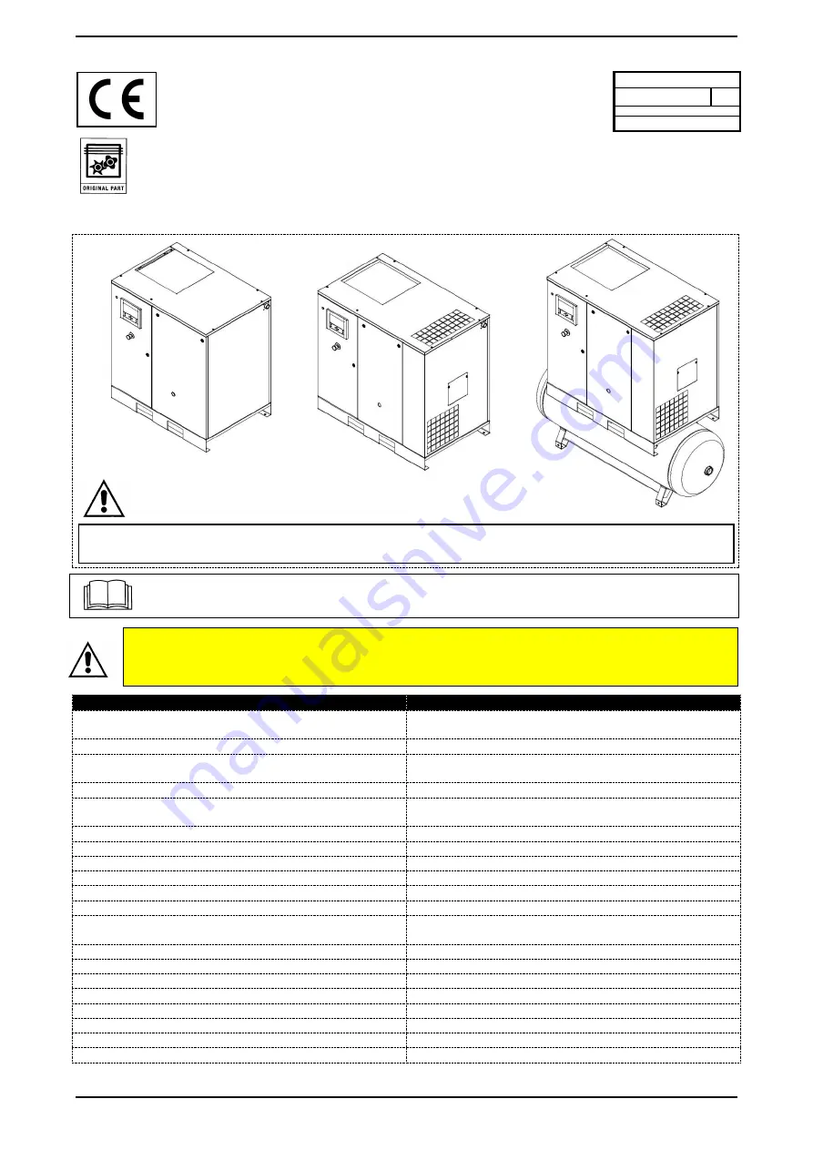
ILLUSTRATION OF MACHINE 


15.0 

ROUTINE MAINTENANCE BY THE USER 


16.0 

STORAGE 


17.0 

DISMANTLING THE AIR COMPRESSOR 


18.0 

SPARE PARTS LIST FOR ROUTINE MAINTENANCE 


19.0 

TROUBLESHOOTING AND IMMEDIATE ACTIONS 


Code 

9828093300   00 


Vers. 04/2019 


READ THIS MANUAL CAREFULLY BEFORE PERFORMING ANY OPERATIONS ON THE AIR COMPRESSOR. 


THIS MACHINE IS DESIGNED TO BE CONNECTED TO TWO DIFFERENT SOURCES OF ELECTRICAL POWER: THREE-PHASE 

POWER SOURCE FOR COMPRESSOR, SINGLE PHASE POWER SOURCE FOR DRYER


Summary of Contents for HP 20

Page 1: ...IL FILTER AND OIL SEPARATOR FILTER REPLACEMENT 5 0 DESCRIPTION OF HAZARD SYMBOLS 24 0 MOTOR BEARING GREASING IVR ONLY 6 0 HAZARDOUS AREAS 25 0 OLEO PNEUMATIC DIAGRAM 7 0 SAFETY DEVICES 26 0 DRYER CALIBRATIONS 8 0 POSITION OF LABELS 27 0 VARIABLE SPEED IVR 9 0 COMPRESSOR ROOM 10 0 TRANSPORT HANDLING 11 0 UNPACKING ATTENTION A COPY OF THE WIRING DIAGRAMS IS INCLUDED IN THE ELECTRICAL CABINET OF THE ...

Page 2: ...LLATION THIS MACHINE SATISFIES THE ESSENTIAL HEALTH AND SAFETY REQUIREMENTS OF EUROPEAN DIRECTIVE 2006 42 EC LUBRICATING FLUIDS AND ANY OTHER FLUIDS MUST NEVER BE DISCHARGED IN THE ENVIRONMENT THESE PRODUCTS CONSIDERED POLLUTING AND HAZARDOUS MUST NECESSARILY BE DISPOSED OF BY AUTHORISED COMPANIES SPECIALISED IN THE DIFFERENT TYPES OF PRODUCT SORT THE PARTS CONSTITUTING THE AIR COMPRESSOR BASED ON...

Page 3: ...oil separator where the oil is separated from the compressed air the latter is filtered again by the oil separator cartridge to reduce the suspended oil particles to a minimum At this point the two flows of oil and air are sent to two distinct coolers where they are cooled using an air flow withdrawn from the outside using a special fan inside the machine The cooled oil is then recirculated while ...

Page 4: ...ARTS 3 NON RESPIRABLE AIR 8 ROTATING FAN 4 NOISE 9 MACHINE WITH AUTOMATIC RESTART 5 HIGH PRESSURE 10 PURGE CONDENSATE DAILY 5 1 DESCRIPTION OF OBLIGATION SYMBOLS 11 READ THE USE MAINTENANCE INSTRUCTIONS 6 0 HAZARDOUS AREAS 6 1 HAZARDOUS AREAS FOR SCREW COMPRESSOR Hazards present on entire machine 1 2 3 5 8 FIG 1 2 2 1 8 2 5 3 2 IVR 2 ...

Page 5: ... SAFETY DEVICES 7 1 SAFETY DEVICES FOR SCREW COMPRESSOR Fig 3 1 Security screws 4 Self locking twist to release emergency button 2 Panel and door to electrical cabinet openable with special key 5 Oil fill cap with breather 3 Fixed fan protection 6 Safety valve 1 2 3 5 8 FIG 2 FIG 3 4 5 3 3 2 1 6 3 2 8 5 5 2 2 3 5 1 2 ...

Page 6: ... 8 0 POSITION OF LABELS 8 1 POSITION OF HAZARD LABELS FOR SCREW COMPRESSOR The labels applied to the compressor unit are part of the machine and have been applied for safety reasons and must not be detached or ruined for any reason whatsoever 1 Hazard label Cod 1079 9903 48 2 Label Machine with automatic restart 2202 2607 91 FIG 4 FIG 5 1 2 1 3 FIG 5 2 1 2 ...

Page 7: ...ave been applied for safety reasons and must not be detached or ruined for any reason whatsoever 1 Generic hazard label Cod 1079 9903 48 2 Machine with automatic restart label Cod 2202 2607 91 3 Multiple voltage label Cod 2202 8731 04 cULus only 4 Risk of electrical shock Cod 2203 0541 10 cULus only 4 Risk of electrical shock CE only FIG 6 2 2 4 3 1 4 ...

Page 8: ...00 00 8 3 POSITION OF INFORMATIVE LABELS FOR SCREW COMPRESSOR 1 Data plate 2 Direction of rotation 3 Drain condensate water 4 General hazards FIG 7 Direction of rotation with fixed speed 2 Direction of rotation with variable speed IVR 2 ...

Page 9: ... allow the evacuation of hot air the second opening must be positioned down low to allow the intake of external ventilation air In the case of dusty environments it is recommended to install a panel filter on these openings 9 3 EXAMPLES OF COMPRESSOR ROOM VENTILATION 10 0 TRANSPORT HANDLING The machine must be transported as specified in the following figures 11 0 UNPACKING After having removed th...

Page 10: ...achine with utmost care in compliance with current standards Such cables must be developed as indicated by the machine s wiring diagram Check the cables connected to the terminal block of the electrical cabinet and make sure they are properly tightened tightening torque provided in wiring diagram The torque of the electrical terminal screws must be checked after the first 50 running hours ACCESS T...

Page 11: ...INSTALLATION The automatic condensate drainage of the air dryer Ref 2 manual drainage of the air tank Ref 4 and automatic drainage of the WSD cyclone water separator optional Ref 3 version with dryer in Fig 12 is conveyed outside the machine by way of flexible and inspectable tubing Drainage must comply with local legislation in force THE MANUFACTURER SHALL NOT BE LIABLE FOR ANY DAMAGE CAUSED BY F...

Page 12: ...VR HP 25 kW 18 5 410 903 8 380 837 7 IVR HP 30 kW 22 425 936 9 390 859 8 IVR HP 35 kW 26 440 970 405 892 8 IVR 500 LT TANK WITHOUT DRYER Dimensions mm in Air couplings L W H D HP 20 35 kW 15 26 1950 76 7 835 32 9 1835 72 2 1 Weight Kg Lb HP 20 kW 15 505 1113 3 485 1069 2 IVR HP 25 kW 18 5 530 1168 4 500 1102 3 IVR HP 30 kW 22 545 1201 5 505 1113 3 IVR HP 35 kW 26 560 1234 5 525 1157 4 IVR 500 LT T...

Page 13: ...m3 h 172 152 127 212 189 145 237 213 180 251 248 198 Noise dB A 68 70 71 72 Oil thermostat calibration C F 115 C 239 F 115 C 239 F 115 C 239 F 115 C 239 F Oil load lt Gal 10 lt 2 64 Gal 10 lt 2 64 Gal 10 lt 2 64 Gal 10 lt 2 64 Gal Dryer type Load R 410A Kg Lb Rated Power W HP MAX bar Psi 50 Hz 60 Hz 50 Hz 60 Hz 50 Hz 60 Hz 50 Hz 60 Hz E8V See dryer data plate 795 1 07 835 1 12 55 0 07 65 0 09 850 ...

Page 14: ...cher 12 Oil catcher 13 Electronic control board 14 Safety valve 15 Fan motor 16 Electric motor 17 Screw compressor 18 Air intake unit 19 Manual condensate drain for air tank 20 Cyclone water separator WSD Optional IT IS PROHIBITED TO TAMPER WITH THE CALIBRATION OF THE SAFETY VALVE 21 Refrigeration compressor 22 Capacitor 23 Fan motor 24 Evaporator 25 Automatic condensate drain 26 Hot gas bypass va...

Page 15: ...T THE MACHINE IMMEDIATELY AFTER A STOP WAIT AT LEAST 20 SECONDS Introduction the controller performs the following functions Control the compressor and dryer Protect the compressor and dryer Monitor servicing Automatic restart after network voltage failure optional mode Automatic control of compressor The controller keeps the output pressure within programmed limits controlling the loading and unl...

Page 16: ...et key Key to reset the service timer a fault condition or to return to the previous display view 5 Enter key Key to select or confirm a parameter to enter a sub menu in the display 6 Voltage present LED Indicates the presence of voltage in the electrical cabinet 7 Voltage present symbol 8 General alarm LED This is on in the presence of an alarm condition It flashes in the presence of a fault or e...

Page 17: ...d When the compressor is running the icon rotates 5 Screw compressor output temperature 6 Dew point version with dryer 7 Motor overload or incorrect phase connection or overtemperature of screw compressor detected by thermostats TSHH11 12 8 Emergency stop command activated 9 Pictogram service 10 Remote Start Stop 11 LAN network setting 12 Automatic restart after voltage failure active 13 Timer Mai...

Page 18: ...TENTION the unit must be isolated from the mains Inspect the compressor to identify and eliminate the fault The alarm message disappears once the fault conditions have been eliminated Dew point temperature For compressors with incorporated dryer if the dew point temperature exceeds the alarm limit non programmable value LED 8 turns on and the relative pictogram appears intermittently The screen sh...

Page 19: ...olating the unit ATTENTION the unit must be isolated from the mains Inspect the compressor to identify and eliminate the fault Once the fault has been eliminated and normal conditions are restored reconnect the power and restart the compressor Motor overload In case of a motor overload the compressor will stop LED 8 turns on LED 10 automatic operation tuns off The following type of screen will app...

Page 20: ...appears then press the enter key 5 The screen shows the unit of measure used hrs or x1000 hrs and the value 1191 the compressor has worked for 1191 hours since the last service Reset service timer Scroll through the screens until reaching d 06 and press the enter key 5 The reading will appear for example 4000 Press the enter key 5 Insert the password on request The reading will flash this indicate...

Page 21: ...trol and channels for Mk 4 and Mk 5 P 3 IP address gateway and subnet mask setting P 4 Pressure band setting P 5 Pressure band selection setting P 6 Modification of service interval P 7 Unit of temperature setting P 8 Unit of pressure setting P 9 Function selection automatic restart after voltage failure P 10 P 11 Load delay setting P 12 Minimum stop time setting P 13 Password setting P 14 Remote ...

Page 22: ...erature 18 Unit of temperature 4 Digital input status 19 Unit of pressure 5 Running Hours 20 Automatic restart 6 Motor starts 21 7 Module hours 22 Load delay 8 Loading hours 23 Minimum stop time 9 Load relay 24 Password settings 10 Service timer reading 25 Remote pressure reading 11 Actual programme version 26 Protections 12 LAN selection 27 Display test 13 Node ID settings 28 Safety valve test 14...

Page 23: ... Monitor servicing Automatic restart after network voltage failure optional mode Automatic control of compressor The controller keeps the output pressure within programmed limits controlling the loading and unloading compressor modes Various set parameters are taken into account including unloading and loading pressure minimum stop time and maximum number of motor starts Protection of compressor F...

Page 24: ...b menu in the display 6 Voltage present LED Indicates the presence of voltage in the electrical cabinet 7 Voltage present symbol 8 General alarm LED This is on in the presence of an alarm condition It flashes in the presence of a fault or emergency stop 9 Alarm symbol 10 Automatic operation LED Indicates that the controller is making the compressor work in automatic mode The compressor is placed i...

Page 25: ...nt version with dryer 7 Alarm generated by inverter or overtemperature of screw compressor detected by thermostat TSHH 11 12 8 Emergency stop command activated 9 Pictogram service 10 Remote Start Stop 11 LAN network setting 12 Automatic restart after voltage failure active 13 Timer Main screen When the board is powered the main screen automatically appears showing the operating status of the compr...

Page 26: ...e For compressors with incorporated dryer if the dew point temperature exceeds the alarm limit non programmable value LED 8 turns on and the relative pictogram appears intermittently The screen shows the dew point temperature Press key 14 until the current dew point temperature appears The screen shows that the dew point temperature is 22 C 72 F Using keys 14 and 15 it is possible to scroll throug...

Page 27: ...tic operation tuns off The following type of screen will appear Attention The Motor overload symbol appears in the case of an inverter alarm an overtemperature detected by thermostat TSHH 11 12 and an overload generated by the fan motor protection Disconnect the power upstream isolating the unit ATTENTION the unit must be isolated from the mains Inspect the compressor to identify and eliminate the...

Page 28: ... since last service Starting from the main menu Press the scroll down key 14 until the screen d 06 appears then press the enter key 5 The screen shows the unit of measure used hrs or x1000 hrs and the value 1191 the compressor has worked for 1191 hours since the last service Reset service timer Scroll through the screens until reaching d 06 and press the enter key 5 The reading will appear for exa...

Page 29: ... 1000 hours d 7 Number of emergency stops d 8 Actual programme version Parameter screens Name Associated topic P 1 Choice of local remote or LAN control P 2 Node ID setting for LAN control and channels for Mk 4 and Mk 5 P 3 IP address gateway and subnet mask setting P 4 Pressure band setting P 5 Pressure band selection setting P 6 Enable remote selection of pressure band P 7 Reduce maximum motor s...

Page 30: ...ENGLISH 30 Vers 04 2019 Cod 9828093300 00 Menu sequence ...

Page 31: ...Digital input status 20 Reduce maximum motor speed 5 Motor speed 21 Service interval setting 6 Running hours 22 Unit of temperature 7 Motor starts 23 Unit of pressure 8 Module hours 24 Autorestart 9 Loading hours 25 Password setting 10 Load relay 26 Protections 11 Service timer reading 27 Display test 12 Number of emergency shutdowns 28 Safety valve test 13 Software version 29 Enable bearing greas...

Page 32: ...than the programmed shutdown value measured by the temperature sensor Screw compressor temperature higher than the programmed shutdown value measured by the thermostats TSHH11 12 Main motor overload Phase sequence relay fixed speed only Fault in one of sensors incorrect Pressure or Temperature display Fan motor overload The chapter Fail stop display explains how the stop is shown on the display ho...

Page 33: ...his turns on when a warning condition occurs 6 Voltage present symbol 7 LED voltage supplied Indicates the presence of voltage 8 Service symbol 9 LED service This turns on when servicing is needed 10 Start Button This button starts the compressor The automatic operation LED 3 turns on The controller is working 11 Stop Button This button is used to stop the compressor The automatic operation LED 3 ...

Page 34: ...g mode Loading mode Machine control modes Or Local start stop Remote start stop Network control Automatic restart after voltage failure Automatic restart after voltage failure active Weekly timer Weekly timer active Protection functions active Emergency shutdown Safety shutdown Alarm Service Service warning Main screen display Display icon with rows of numeric values Chart display icon General ico...

Page 35: ...ion Icon Description Input Historical events saved data Output Access key User password Protections Warnings shutdowns Network Counters Regulation point Test Information Regulation Settings Weekly timer Service General Navigation arrows Icon Description Icon Description Screw compressor LP HP Motor Dryer Expansion module failure Fan Network problem Inverter General alarm Up Down ...

Page 36: ...ed as a of the maximum flow Section B shows the status icons This field generally shows the following icons Fixed icons These icons are always displayed in the main screen and cannot be selected using the cursor for example compressor stopped or running compressor status running in unloading mode or motor stopped Optional icons These icons are only displayed if the corresponding function has been ...

Page 37: ...ut per day The screen shows the variations over the last 10 days Main screen selection To move between the various layouts of the screen select the rightmost icon in the row of command icons see value lines display icon or chart display icon in the Icons used section and press the Enter button A screen will appear similar to the one shown below Select the desired icon and press the Enter key See a...

Page 38: ... the fault condition has been eliminated Shutdown display In case of a shutdown a red icon appears in the bottom part of the display as shown in the left hand side figure below To identify the cause of the shutdown highlight the red icon 1 using the scroll buttons Press Enter and the Protections menu will appear as shown in the right hand side figure above Press Enter and the list of active protec...

Page 39: ...nction X X Fan malfunction 30 U phase loss X X U phase of motor does not exist Check phase 31 V phase loss X X V phase of motor does not exist Check phase 32 W phase loss X X W phase of motor does not exist Check phase 36 Voltage drop X X Problem with supply 38 Internal fault X X Compressor contact service 44 Ground fault X X Discharge from output phases to ground Request assistance from the distr...

Page 40: ...he cursor onto the Menu action button and press the Enter key Using the scroll keys move the cursor onto the Inputs icon as shown in the screen below Press the Enter key A screen will appear similar to the one shown below The screen displays a list of all the inputs with the relative icons and values If an input is found in an alarm or stop condition the original icon is replaced by the respective...

Page 41: ...number of controller running hours and the number of loading cycles Procedure from the Main screen see main Screen move the cursor onto the Menu action button and press the Enter key Using the scroll keys move the cursor onto the Counters icon see below Press the Enter key A screen will appear similar to the one shown below The screen displays the list of all counters and the relative effective va...

Page 42: ... the scroll buttons move to the status icons and select the regulation icon 2 The icon is active when it is highlighted on a grey background Press the Enter button There are 2 possibilities Local control LAN network control After having selected the requested Regulation Mode press the Enter key on the controller to confirm the selection The new setting is now visible on the main screen See the Ico...

Page 43: ...ervals Procedure from the Main screen see main Screen move the cursor onto the Menu action button and press the Enter key Using the scroll keys move the cursor onto the Service icon see below Press the Enter key A screen will appear similar to the one shown below Scroll the items to select the desired item and press the Enter key to view the details as explained above 1 Service 2 Overview 3 Servic...

Page 44: ...ervice operations are grouped level A level B etc Each level entails a series of service operations that need to be carried out in accordance with deadlines programmed into the controller When the service plan interval is reached a message is shown on the screen After having performed the service operations relative to the indicated levels the timers need to be reset From the Service menu select S...

Page 45: ...nloading and loading pressure settings for both pressure bands To change the settings move the cursor onto the Modify action button and press the Enter key The following screen appears The first row of the screen is highlighted Use the scroll keys to highlight the setting to be changed and press the Enter key The following screen appears The upper and lower limits of the setting are shown in grey ...

Page 46: ...er data relative to the compressor status at the time of the shutdown Modification of general settings Calibrations Function allows the viewing and modification of certain general settings Procedure from the Main screen see main Screen move the cursor onto the Menu action button and press the Enter key Using the scroll keys move the cursor onto the Settings icon see below Press the Enter key A scr...

Page 47: ...that they don t occur simultaneously after a voltage failure condition ARAVF active Screw compressor outlet The regulator does not accept conflicting settings For example if the alarm level is programmed at 95 C 203 F the minimum shutdown level will become 96 C 204 F The recommended difference between the alarm level and shutdown level is 10 C 18 F Shutdown delay This is the period of time during ...

Page 48: ...lter Clean the condenser coil for dryer if present Clean the impurity filter of the automatic condensate drain dryer Every 2000 hours Replace the intake filter Replace the oil Replace the oil filter Re tightening of electrical cables in cabinet Temperature test for safety Replace the impurity filter of the automatic condensate drain dryer Every 4000 hours Clean the finned surface of the air oil co...

Page 49: ...ate to drain When the first traces of oil appear close the tap CONDENSATE MUST BE DISPOSED OF IN ACCORDANCE WITH LOCAL REGULATIONS IN FORCE Check the oil level using the tell tale Ref 6 Fig 17 If the oil level is below the minimum top it up as described in point 15 4 15 4 OIL LEVEL CONTROL AND TOP UP Shut down the machine using the button Ref 1 Fig 17 in this way the machine will stop after the un...

Page 50: ... foam level is roughly in the middle of the sight glass Machine stopped for a few minutes As soon as the foam disappears the sight glass must be almost completely covered ATTENTION Do not check the oil level on a machine stopped for more than 10 minutes Do not add any extra oil ...

Page 51: ...Ref 4 Fig 18 Clean the electrical cabinet filters with a blast of air or wash with water Do not use solvents After this operation remount the filters Ref 4 Fig 18 AIR INTAKE PANEL FILTER CLEANING Shut down the machine using the button Ref 1 Fig 18 in this way the machine will stop after the unloading run time Open the power disconnect switch Ref 3 for screw compressor and Ref 3A for dryer if prese...

Page 52: ...h Ref 3 for screw compressor and Ref 3A for dryer if present Fig 18 HOT INTERNAL PARTS Open the panel Ref 2 Fig 18 Remove the filter cover Ref 7 Fig 19 Remove the filter element Ref 8 Fig 19 DO NOT ALLOW FOREIGN BODIES TO FALL INTO THE INTAKE MANIFOLD Clean the filter element with a blast of air from the inside out DO NOT USE WATER OR SOLVENTS or grab a new filter Clean the filter support disc wit...

Page 53: ...drain Service See Chap 15 8 If normal drain operation is not restored after the drain service GREEN LED contact the customer centre 15 8 DRAIN SERVICE IMPURITY FILTER CLEANING FOR DRYER IF INCLUDED Proceed as follows Shut down the machine using the button Ref 4 Fig 20 in this way the machine will stop after the unloading run time Close the tap Ref 5 Fig 20 machine with without tank Remove the pane...

Page 54: ...TRIBUTION NETWORK The capacitor must be cleaned every month Proceed as follows Shut down the machine using the button Ref 1 Fig 21 in this way the machine will stop after the unloading run time Open the power disconnect switch Ref 2 compressor and Ref 3 for dryer Fig 21 Vacuum any dust deposits on the capacitor fins through the panel grill Ref A Fig 21 DO NOT USE WATER OR SOLVENTS HOT INTERNAL PAR...

Page 55: ...having completely discharged the air under residual pressure Disconnect the power supply using the disconnect switch Ref 4 for screw compressor and Ref 5 for dryer if included Fig 22 During downtime the machine must be protected against atmospheric agents dust and humidity which may damage the motor and electrical system Moreover the compressor must be placed into operation once per month For the ...

Page 56: ...18 5 HP 30 kW 22 HP 35 kW 37 1 Air oil separator filter 1 6221 3724 50 1 Air oil separator filter 1 6221 3725 50 2 Oil filter 1 6211 4722 50 3 Intake filter 1 6211 4723 50 4 Electrical cabinet filters IVR only 2 1089 9556 70 5 Air intake panel filter 1 2204 1213 01 Motor bearings tube IVR only 4 1630 2023 00 2 3 FIG 23 2 1 4 5 ...

Page 57: ... 4 The compressor doesn t reach the working pressure 4A the compressed air consumption in the network is too high 4B the loading unloading solenoid valve remains closed check the electrical system 5 Excessive oil consumption 5A worn oil separator filter oil level too high replace the oil separator filter Chap 23 19 2 TROUBLESHOOTING AND IMMEDIATE ACTIONS FOR SCREW COMPRESSOR Graphic table for fixe...

Page 58: ...Refrigeration compressor head very hot 55 C and the control board shuts it down due to a high dryer temperature alarm See 2B See 2C 3A The cooling circuit is not working with the right gas load Check for any refrigerant gas leaks Load again 4 The refrigeration compressor works intermittently due to the intervention of the Klixon protector See 2B See 2C See 3A 5 The refrigeration compressor hums an...

Page 59: ...level is less than expected top it up with the same oil as the original type See chap 15 4 If the period of time between factory commissioning and the installation date is greater than 3 months re lubricate the screw unit before starting it up following the procedure below Remove the intake filter cover Ref 2 Fig 24 Remove the filter element Ref 3 Fig 24 Pour some oil into the intake unit Remount ...

Page 60: ... electrical connection wires phases If the direction of rotation is correct the oil level Ref 5 Fig 25 must drop after 4 5 seconds of operation Moreover it is very important to check the direction of rotation of the fan indicated by the arrow on the latter Ref 6 Fig 25 ALL OPERATIONS ON THE ELECTRICAL SYSTEM EVEN IF MINOR MUST BE PERFORMED BY PROFESSIONALLY QUALIFIED PERSONNEL It is recommended no...

Page 61: ...ondenser coil for dryer if present Clean the impurity filter of the automatic condensate drain dryer Every 2000 hours Replace the intake filter Replace the oil Replace the oil filter Re tightening of electrical cables in cabinet Temperature test for safety Replace the impurity filter of the automatic condensate drain dryer Every 4000 hours Clean the finned surface of the air oil cooler Replace the...

Page 62: ...g 26 after the unloading run time the machine will turn off PROCEED AS DESCRIBED IN CHAPTER 15 4 USED OIL MUST BE DISPOSED OF IN ACCORDANCE WITH REGULATIONS IN FORCE NOTES ON LUBRICANTS The machine is supplied already filled with oil Prolonged use of the lubricant beyond the prescribed service period may entail the risk of fire In case of use at high temperatures or particularly heavy duty service...

Page 63: ...period of about 60 seconds from the complete shutdown of the machine Open the power disconnect switch Ref 3 for screw compressor and Ref 4 for dryer if present Fig 27 Close the tap Ref 5 Fig 27 machine with and without tank Depressurise the compressor by unscrewing the cap of the filling inlet Ref 1 by one turn so as to discharge any residual pressure in the system Depressurise the dryer and tank ...

Page 64: ... as follows Restore the power supply Activate the lubrication programme from the MK5 menu Select the lubrication function password 1807 Go back to the main menu and press START Ref 4 Fig 29 The compressor will run the lubrication programme in unloading mode for 15 minutes at 1700 rpm From the lubrication menu the operator can check the remaining time N B During lubrication it is not possible to st...

Page 65: ...ate the lubrication programme from the controller menu Scroll down using the arrow until parameter t 03 Select the lubrication function password 1807 Go back to the main menu and press START Ref 4 Fig 29 The compressor will run the lubrication programme in unloading mode for 15 minutes at 1700 rpm N B During lubrication it is not possible to stop the machine using the STOP key Ref 5 Fig 29 In any ...

Page 66: ...INTAKE UNIT 13 FAN 3 ELECTRIC MOTOR 14 AIR TANK 4 SCREW COMPRESSOR 15 AIR TANK SAFETY VALVE 5 OIL TANK 100 CONTROL BOARD 6 AIR OIL SEPARATOR FILTER 200 AIR DRYER 7 SAFETY VALVE 210 SEPARATOR FILTER OPTIONAL 8 OIL DRAIN 220 LINE FILTER OPTIONAL 9 MINIMUM PRESSURE VALVE 10 NON RETURN VALVE 11 THERMOSTATIC VALVE ...

Page 67: ... 55 105 6 109 5 26 1 DRYER FLOW DIAGRAM 1 REFRIGERATION COMPRESSOR 8 FREON FILTER 2 CAPACITOR 9 HOT GAS BYPASS VALVE 3 FAN MOTOR 10 AIR AIR EXCHANGER 4 EVAPORATOR 11 DEW POINT THERMOMETER 5 SEPARATOR 12 FAN PRESSURE SWITCH 7 CAPILLARY TUBE 27 0 VARIABLE SPEED The Variable speed version of the machine is controlled by an INVERTER The equipment is factory calibrated and does not require any adjustme...

Reviews: