


1. Power source stops
2. No weld current, fuse blowing in 13 amp plug
3. No weld current
4. Feed motor not working, lamp is on
5. Wire does not feed, feed roller rotates
6. Wire feeds unevenly.
7. Unstable arc.
8. Porous weld
9. Electrode sticking in gas cup (nozzle)
10. Irregular weld head
11. Weld bead too narrow and raised
12. Weld bead too wide
13. Poor penetration
14. Excessive penetration
15. Fuse blowing
Overheating protection activated due to overload
Rectifier blown
Bad connection between clamp and workpiece
Break in earth lead
Break in torch lead
Motor fuse blown
Gear damaged or worn
Motor defective
Pressure roller incorrectly adjusted
Dirt, copper, dust, etc, have collection in torch liner
Gas cup (Nozzle) or tip defective
Deformed wire
Dirt, etc, in liner
Gas cup (Nozzle) or tip defective
Gas cup (Nozzle) spattered
Feed roller groove clogged
Feed roller groove deformed
Pressure roller tension incorrect
Incorrect settings
Impurities in weld area
Worn or defective gas cup (nozzle)
No gas
Gas cup clogged
Draft blowing away shielding gas
Rusty or dirty joints
Torch too far from workpiece
Gas leak
Worn or defective gas cup (nozzle)
Electrode deformed
Wire speed too slow
Torch incorrectly held
Wire weaving in weld pool
Weld current too high
Weld speed too low
Weld current too high
Weld speed too low
Arc too long
Weld current too low
Arc too long
Weld current too high
Weld speed too slow
Incorrect distance of torch to workpiece
Tension too great
Gas cup contact tip clogged
PROBLEM
POSSIBLE CAUSE
REMEDY
10. TROUBLESHOOTING
Protection automatically resets when transformer has cooled
(about 15min).
Replace rectifier.
Clean or grind contact surface and weld area.
Repair or replace earth lead.
Repair or replace torch.
Replace fuse.
Replace gears (Section 9).
Replace motor (Contact service agent).
Adjust tension (Section 4).
Clean the liner from the machine forward. Use compressed air. If
too much dirt, replace the liner (Section 9).
Replace gas cup (nozzle) and/or tip (Section 9).
Check roller tension and adjust it if necessary (Section 4).
Clean the liner from the machine forward. Use compressed air.
Replace gas cup (nozzle) and/or tip (Section 9).
Clean or replace gas cup (nozzle) (Section 9).
Clean feed roller (Section 9).
Replace feed roller (Section 9).
Adjust tension (Section 4).
Use correct settings.
Clean and/or grind workpiece (Section 5).
Replace gas cup (nozzle) (Section 9).
Open gas cylinder, regulate gas flow.
Clean or replace cup (Section 9).
Screen off welding site or increase gas flow.
Clean or grind the workpiece (Section 5).
The distance from gas cup to workpiece should be 8-10mm.
Check hoses, connections and torch assembly.
Replace gas cup (nozzle) (Section 9).
Check roller tension (Section 4).
See recommendations for wire speed. (Section 5).
Use correct torch angle (Section 8).
Check roller tension and adjust as needed (Section 4).
Increase power and wire speed (Section 5).
Move torch slower and weave a little more.
Decrease power and wire speed (Section 5).
Move torch faster and weave less.
Bring torch closer to workpiece.
Increase power and wire speed (Section 5).
Bring torch closer to workpiece.
Decrease power and wire speed (Section 5).
Move torch faster.
Torch distance should be 8-10mm.
Reduce tension (Section 4).
Clean gas cup and contact tip (Section 9).
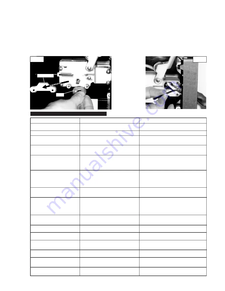
fig. 12
Plastic cover
Roller
fig. 13
9.6.
Replacing torch body.
Remove hook and four screws on handle. Pull apart, pull out torch body. Disconnect gas hose, wire liner and
switch cable. Unscrew swan-neck. Fit new body.
9.7.
Replacing wire liner.
Wind the wire back on to the spool and secure it. Remove three screws securing torch cable to wire feed unit.
Take off plastic cover (fig. 13). Undo the torch case and disconnect wire liner from torch head. Pull out the liner and insert new one. Reverse
the process to re-assemble and trim liner as close to the feed roller as possible.
9.8.
Changing gears.
An inexperienced welder can allow spatter to build up in the tip and shroud. In severe cases this can block
the wire feed causing gear stripping in the drive motor. To check if the gears are worn depress the button on the torch with the set switched
on. If the gears are worn, a grating sound will be heard coming from the wire feed motor, you may also observe the feed roller vibrating
instead of rotating. Should this be the case, open the gearbox, remove the worn or damaged gears and replace with new ones.
PMG100.V2, PMG110.V2, PMG135XT.V2, PMG155XT.V2 - 2 - 120407


