


6. CONVERSION TO MIG (GAS) WELDING
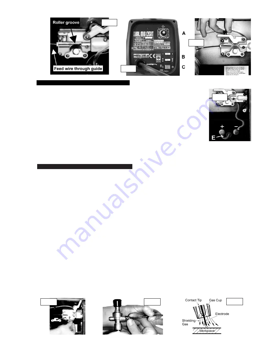
fig. 11
For welding stainless steel or aluminium, the gasless mig welder (with the exception of model PMG100) can be converted to a conventional mig
welder. To convert to gas, just order a reel of regular wire, a bottle of gas and a conversion kit. Kit contains regulator plus tips and nozzles.
6.1.
Welder conversion
6.1.1. Ensure that the welder is disconnected from the mains power supply and open the side panel. Re-connect the power leads as follows.
Remove the earth clamp cable from the POSITIVE (+) terminal (fig. 8.E) and the power (torch) cable from the NEGATIVE (-) terminal.
Connect the earth to the NEGATIVE terminal and the power (torch) cable to the POSITIVE terminal.
6.1.2. Remove flux cored wire and fit steel wire (0.6 or 0.8mm).
6.1.3. If necessary, remove wire feed roller retaining screws and bracket and turn roller (fig. 9) so that the appropriately sized groove is
towards the outside.
6.1.4. Tension as in para. 4.4.
6.2. Gas
cylinder
6.2.1. Fit the chrome plated wire carrier to the back of the machine by pressing together and releasing it into the slots provided.
6.2.2. Screw the flow regulator onto the cylinder
(finger tight only
). Once the cylinder has been opened (sound of gas escaping) screw the
flow regulator a further full turn, which is sufficient to seal the cylinder.
#
WARNING! Excessive tightening of the flow regulator will over-compress the rubber sealing washer and
allowing the gas to escape slowly without being detected.
6.2.3. Push the gas hose into the regulator outlet, it will seal automatically. To release the gas hose, press the collar on the quick coupler and
pull the hose (fig. 10).
6.2.4. With the set on, turn the regulator knob halfway for 2ltr/min and all the way for maximum of 4ltr/min.
6.2.5. Always remove the flow regulator after use if the machine is to be stored for any length of time.
6.3.
Gas types
Welding mild steel with CO
2
gas is appropriate for most welding tasks where spatter and high build up of weld do not pose a problem.
To achieve a spatter-free and flat weld however, you must use an CO
2/
Argon mixture.
To weld aluminium use:
"
Argon gas
"
0.8mm Contact Tip
"
0.8mm Aluminium Wire (MIG/2/KAL08)
6.4.
Other
You can use large industrial gas cylinders if preferred (the machine is no longer portable). To do so, contact your local Sealey dealer
to obtain an industrial regulator and cylinder adaptor kit.
fig. 9
fig. 10
#
WARNING! ENSURE THAT YOU READ, UNDERSTAND AND APPLY SAFETY INSTRUCTIONS
BEFORE OPERATING THE MACHINE. IF WELDING A VEHICLE, DISCONNECT THE
BATTERY OR FIT AN ELECTRONIC CIRCUIT PROTECTOR.
5.1.
Ensure that the welder is disconnected from the main power supply, open the side panel and check that
the earth clamp wire is connected to the POSITIVE (+) terminal and the power (torch) lead is connected
to the NEGATIVE (-) terminal (fig. 8).
5.2.
To ensure a complete circuit, the earth clamp must be securely attached to the workpiece.
a) Obtain the best connection by grinding the point of contact on the workpiece before connecting the clamp.
b) The weld area must also be free of paint, rust, grease, etc.
5.3.
If welding a vehicle, disconnect the battery or fit a “Electronic Circuit Protector” (available from your
Sealey dealer).
5.4.
Wire feed switch controls the speed of wire feed. The lower the power setting, the slower the wire speed.
5.5.
Power settings are Min/ 1 (low), Min/2, Max/1, Max/2 (high), (fig. 5) - set the wire speed accordingly.
Wire from the spool is automatically fed through an insulated liner in the torch to the tip. The torch assembly consists of a switch, wire
liner, gas hose (not PMG100) and control cable. The switch activates the wire feed roller (to stop wire feed release the switch). As wire
comes into contact with the workpiece an arc is struck. The arc melts the wire which is deposited into the weld.
5. GASLESS OPERATION
fig. 7
fig. 8
fig. 5
fig. 6
PMG100.V2, PMG110.V2, PMG135XT.V2, PMG155XT.V2 - 2 - 120407


