background image

   1)  Install the rubber grommets and brass

collets onto the elevator, rudder and throttle
servos.  Test fit the servos into the preinstalled
servo tray. Because the size of servos dif-
fer, you may need to adjust the size of the
precut openings in the tray.


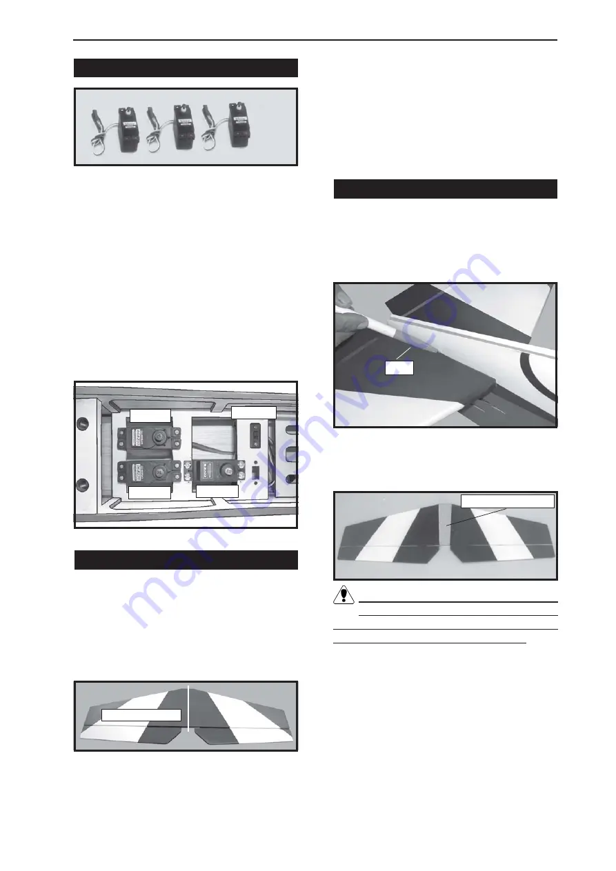
  2) Position the servos into the servo tray

with the output shafts orientated as shown
below.  Drill 1/16” pilot holes through the tray
for each of the mounting screws.

INSTALLING THE FUSELAGE SERVOS.

Secure the servos with the screws pro-

vided from your radio system.

1) Using a ruler and a pen, locate the

centerline of the horizontal stabilizer, at the trail-
ing edge, and place a mark.  Use a triangle
and extend this mark, from back to front,
across the top of the stabilizer.  Also extend
this mark down the back of the trailing edge of
the stabilizer.

ALIGNING THE HORIZONTAL STABILIZER.


2) Using a modeling knife, carefully re-

move the covering from over the vertical sta-
bilizer mounting slot in the top of the fuselage.

4) When you are satisfied with the align-

ment, hold the stabilizer in place with T- pins
or masking tape, but do not glue at this time.

MOUNTING THE HORIZONTAL STABILIZER.

1) With the stabilizer held firmly in place,

use a pen and draw lines onto the stabilizer
where it and the fuselage sides meet.  Do this
on both the right and left sides and top and
bottom of the stabilizer.

2) Remove the stabilizer.  Using the lines

you just drew as a guide, carefully remove the
covering from between them using a model-
ing knife.

When cutting through the covering to re-
move it, cut with only enough pressure

to only cut through the covering itself.  Cutting
into the balsa structure may weaken it.

Remove covering.

3) Using a modeling knife, carefully re-

move the covering that overlaps the stabilizer
mounting platform sides in the fuselage.  Re-
move the covering from both the top and the
bottom of the platform sides.

4) When you are sure that everything is

aligned correctly, mix up a generous amount
of 30 Minute Epoxy.  Apply a thin layer to the
top and bottom of the stabilizer mounting area
and to the stabilizer mounting platform sides

Draw center line.

Pen.

3) Slide the stabilizer into place in the pre-

cut slot in the rear of the fuselage.  The stabi-
lizer should be pushed firmly against the front
of the slot.

Throttle.

Elevator.

Rudder.

Switch.

18

Summary of Contents for SEA12

Page 1: ...arepackincludingwheels tank undercarriage spinner Photo illustratedstep by stepAssemblyManual Hand made Hand made Hand made Hand made Hand made Almost R Almost R Almost R Almost R Almost Read ead ead ead eady to F y to F y to F y to F y to Fl l l l ly R C Model y R C Model y R C Model y R C Model y R C Model Aircraft Aircraft Aircraft Aircraft Aircraft ASSEMBL ASSEMBL ASSEMBL ASSEMBL ASSEMBLY MANU...

Page 2: ...flight we strongly recommend you contact your R C supplier and join your local R C Model Flying Club R C Model Flying Clubs offer a variety of training procedures designed to help the new pilot on his way to successful R C flight They will also be able to advise on any insurance and safety regulations that may apply ADDITIONAL ITEMS REQUIRED 40 58 2 stroke engine 50 72 4 stroke engine 4 channel ra...

Page 3: ...hould lightly contact the wing during this procedure Ideally when the The control surfaces including the ailerons elevators and rudder are prehinged with hinges installed but the hinges are not glued in place It is imperative that you properly adhere the hinges in place per the steps that follow using a high quality thin C A glue 1 Carefully remove the aileron from one of the wing panels Note the ...

Page 4: ...s into both the aileron and wing panel 6 Using C A remover debonder and a paper towel remove any excess C A glue that may have accumulated on the wing or in the aileron hinge area The hinge is constructed of a special material that allows the C A to wick or penetrate and distribute throughout the hinge securely bonding it to the wood structure of the wing panel and aileron hinges are glued in plac...

Page 5: ... in easily up to the centreline that you drew Carefully slide the two wing halves together and firmly press them together allowing the excess epoxy to run out There should not be any gap in the wing halves Use rubbing alcohol and a paper tower to clean up any excess epoxy Apply masking tape at the wing join to hold the wing halves together securely Dihedral brace Centre line 3 Remove the brace whe...

Page 6: ...d and care fully thread it though the wing Once you have thread the lead throught the wing remove the string so it can use for the other servo lead Because the size of servos differ you may need to adjust the size of the precut opening in the mount The notch in the sides of the mount allow the servo lead to pass through Secure the servos with the screws pro vided from your radio system 2 Using a s...

Page 7: ...ood screws provided with you radio system Thread Plastic tape 2 Locate the two nylon control horns two nylon control horn backplates and four machine screws 3 Position the aileron horn on the bottom side of aileron The clevis attachment holes should be positioned over the hinge line Pen Straight line Repeat the procedure for the other wing half 1 Using a ruler pen to draw a straight line as below ...

Page 8: ...h the wood 7 With the aileron servo centered and the aileron even with the trailing edge of the wing attach the clevis to the control horn Mark the control wire where it crosses the servo arm hole 8 Make a 90 degree bend at the mark and cut off the excess wire leaving 10mm past the bend INSTALLING THE MAIN GEAR WIRES 1 Using a modeling knife remove the covering from over the two main gear mount in...

Page 9: ...r straps as a guide mark the locations of the four 3mm x 12mm mounting screws onto the wing sur face 5 Remove the two straps and the gear wire Drill four 3 32 pilot holes into the wing for the wood screws Be careful do not to drill through the top of the wing 8 Slide one 60mm diameter wheel onto each axle and push them up against the wheel collars Slide the remaining wheel collars with 3mm x 6mm s...

Page 10: ...ot bind in any way INSTALLING THE NOSE GEAR WHEEL 1 Using a modeling knife carefully cut off the rear portion of one of the two nylon tubes leaving 1 2 protruding from the rear of the stopper This will be the fuel pick up tube 2 Using a modeling knife cut one length of silicon fuel line not included to 2 1 4 long Connect one end of the line to the weighted fuel pickup and the other end to the nylo...

Page 11: ... knife If flashing is present make sure none falls into the tank 6 With the stopper assembly in place the weighted pickup should rest about 3 8 away from the rear of the tank and move freely inside the tank The top of the vent tube should rest just below the top of the tank It should not touch the top of the tank 7 When satisfied with the alignment of the stopper assembly tighten the 3mm x 20mm ma...

Page 12: ... plastic motor mount 3 Screw 4 pilot holes with 2 5 mm diam eter Fuel fill tube Fuel pickup tube Vent tube 4 Secure your engine on the motor mount by mounting with 4 machine screws 2 5mm 3mm X 25mm 5 Attach the Z Bend in the pushrod wire to the throttle arm on the carburetor You will need to remove the throttle arm from the car buretor to be able to attach the Z bend When complete reattach the thr...

Page 13: ...6 925 Watts Propeller 12x8 14x10 ESC 60A 4S 5S Lipo 3 Attach the electric motor box to the firewall suitable with the cross lines drawn on the electric motor box and fire wall Using epoxy and balsa stick to se cure the motor box to the firewall Please see pictures below 4 Attach the motor to the front of the electric motor box using four 4mm blind nut four M3x15mm hex head bolts to se cure the mot...

Page 14: ...Instruction Manual M3x15mm 11cm Epoxy 14 ...

Page 15: ...Speed control Battery M3x15mm 15 Air exit hole ...

Page 16: ...ed needle valve Make this out of sufficient length 1 5mm wire and in stall it into the end of the needle valve Se cure the wire in place by tightening the set screw in the side of the needle valve 7 Install the muffler and muffler extension onto the engine and make the cutout in the cowl for muffler clearance Connect the fuel and pressure lines to the carburetor muffler and fuel filler valve 2 Whi...

Page 17: ...from the bot tom Use the two screws provided with the switch to secure it in place Drill two 3 32 holes through the tray for the screws to pass through 2 Using a 3 32 drill bit drill a hole through the side of the fuselage opposite the muffler even with the switch INSTALLING THE SWITCH 3 Make a push pull lever out of scrap wire Attach the wire to the switch lever and route the wire out the side of...

Page 18: ...pins or masking tape but do not glue at this time MOUNTING THE HORIZONTAL STABILIZER 1 With the stabilizer held firmly in place use a pen and draw lines onto the stabilizer where it and the fuselage sides meet Do this on both the right and left sides and top and bottom of the stabilizer 2 Remove the stabilizer Using the lines you just drew as a guide carefully remove the covering from between them...

Page 19: ...ng alcohol 2 Slide the vertical stabilizer into the slot in the top of the fuselage The rear edge of the stabilizer should be flush with the rear edge of the fuselage and the lower rudder hinge should engage the precut hinge slot in the lower fuselage The bottom edge of the stabi lizer should also be firmly pushed against the top of the horizontal stabilizer 3 While holding the vertical stabilizer...

Page 20: ...halves then into the mounting backplates Do not overtighten the screws or the backplates may crush the wood 5 Position the rudder control horn on the left side of the airplane 6 Install the rudder control horn using the same method as with the elevator control horns 3 Using a 5 64 drill bit and the control horns as a guide drill the mounting holes through the elevator halves Control Horn Mounting ...

Page 21: ...rubber band and a modified servo arm See picture as below Antenna Rubber Band Modified Servo Arm Cut ATTACHMENT WING FUSELAGE See picture below BALANCING 1 It is critical that your airplane be bal anced correctly Improper balance will cause your plane to lose control and crash The cen ter of gravity is located 8 9 5cm back from the leading edge of the wing at the fuselage sides Balance the PC 9 up...

Page 22: ...t they are on the low rate setting for your first few flights 6 Check to ensure the control surfaces are moving the proper amount for both low and high rate settings 7 Check the receiver antenna It should be fully extended and not coiled up inside the fuselage CONTROL THROWS 1 We highly recommend setting up the PC 9 using the control throws listed below We have listed control throws for both initi...

Reviews: