background image

DAT Autoloader Installation Manual

11

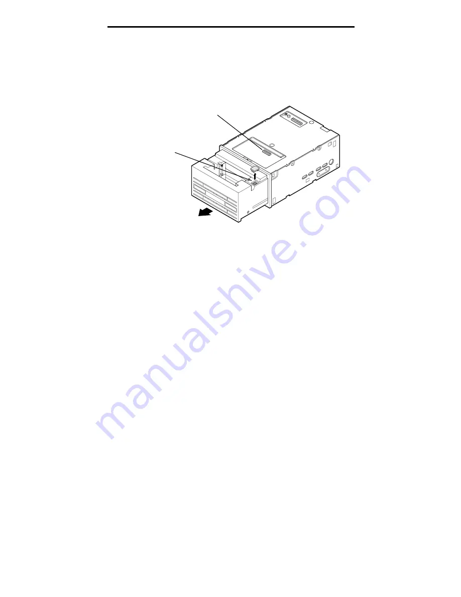
Internal configuration switches

Two additional sets of dip switches are located inside the
autoloader drawer (see Figure 5). These are used to adjust
the 8-character LED display and other settings.

Figure 5. Location of internal dip switches

Cassette

Drive

Open/Close

DC

Write Protect

Step

Bank of seven dip switches
(on top of drawer)

Bank of four dip switches
(below rubber plug)

Note: Drawer must be open
to view switches

To access these switches, you must use the following
procedure.

1.

Power-on the drive.

➤ 

Note. To access the bank of seven dip switches on the
top of the drawer, the drive must be powered on and the
autoloader must be outside of a system enclosure.

2.

Open the autoloader drawer by pressing the Open/Close
button on the front bezel.

3.

Power-off the drive.

4.

Set the appropriate dip switches.

5.

Power-on the drive.

6.

Press the Open/Close button to close the drawer.

Summary of Contents for Scorpion 96

Page 1: ...Scorpion 96 DAT Autoloader Installation Manual 10004447 002 October 1997 Cassette Drive Open C lose DC Write Protect Step...

Page 2: ...Scorpion 96 DAT Autoloader Installation Manual...

Page 3: ...names are registered trademarks or trademarks of their owners Seagate makes no Warranty of any kind with regard to this document Seagate shall not be liable for any errors contained herein or indirect...

Page 4: ...spacer sheet 5 3 Installing the internal autoloader 6 Configuring the internal autoloader 6 Default settings 6 External dip switches 8 Jumpers on back of drive 9 Internal configuration switches 11 Mo...

Page 5: ...Using the Open Close button 23 Front panel LEDs 24 Drive LED amber 25 Cassette LED green 25 Data Compression LED green 26 Write Protect LED green 26 The 8 digit alphanumeric display 26 Autoloader dis...

Page 6: ...it by taking one or more of the following measures Reorient or relocate the receiving antenna Increase the separation between the computer and the receiver Connect the computer into an outlet on a cir...

Page 7: ......

Page 8: ...ations and Chapter 7 summarizes sources of technical support information About the Scorpion 96 autoloader The Seagate internal Autoloader is a fully integrated intelligent multicartridge digital audio...

Page 9: ...types Archival storage Scorpion 96 capacity and data transfer rates The Scorpion 96 provides the following capacities and data transfer rates depending upon the type and length of tape media used Thes...

Page 10: ...nents If you need to put down the drive lay it on top of the antistatic bag or place it inside the bag Unpacking and inspection Although Seagate autoloaders are inspected and carefully packaged at the...

Page 11: ...ive To remove these brackets follow the instructions below and see Figure 1 1 Loosen the two large screws on either side of the horizontal metal bracket attached to the drive faceplate 2 Lift the hori...

Page 12: ...own and remove the two retaining screws as shown in Figure 2 2 Look on the back of the drive to find the tab at the end of the spacer Pull slowly on this tab to slide the plastic spacer out from betwe...

Page 13: ...Scorpion 96 in your computer you may need to configure the drive to work with your system Default settings The default settings for the internal drive are listed below SCSI termination is disabled SCS...

Page 14: ...SI ID MRS checking Parity checking Data compression Power on self test enable Jumpers on the back of the drive SCSI termination Terminator power Remote SCSI address selection Internal dip switches loc...

Page 15: ...7 S9 S10 Default settings Reserved do not use Reserved Data compression Self test Parity MRS Mode Enable Disable Disable Enable Enable Disable Enable Disable SCSI ID Selection OFF ON OFF ON OFF ON OFF...

Page 16: ...bles execution of power on self test POST diagnostics when the autoloader is first powered on If this switch is ON the default the autoloader responds to SCSI commands only after successful completion...

Page 17: ...nator power jumper The terminator power fuse is designed to prevent damage to Autoloader components in case terminator power is shorted For example If terminator power is enabled and the SCSI cable is...

Page 18: ...n top of drawer Bank of four dip switches below rubber plug Note Drawer must be open to view switches To access these switches you must use the following procedure 1 Power on the drive Note To access...

Page 19: ...able below summarizes the functions of the seven dip switches on top of the autoloader drawer Switch Description Default 1 LED display language switch see table below OFF 2 LED display language switch...

Page 20: ...Open Close button on the front bezel After setting the dip switches press the Open Close button to close the drawer You must power down the drive and restart it before the new dip switch settings will...

Page 21: ...that provides an air flow of at least 12 cubic foot minute If the air flow is less than this the autoloader may not function properly Connecting the power cable Attach a standard 5 12 volt 4 pin power...

Page 22: ...PLACES M3 0 X 4 DEEP MIN 2 PLACES 79 5 mm 3 130 in 2 PLACES 47 5 mm 1 871 in 2 PLACES M3 0 X 4mm DEEP MIN 6 PLACES 21 8 mm 859 in 2 PLACES 11 9 mm 469 in 2 PLACES 215 0 mm 8 471 in 2 PLACES 79 5 mm 3...

Page 23: ...te To change these and other advanced drive options you must remove the external autoloader from its case Then set the appropriate jumpers as described in the previous chapter Setting the SCSI ID The...

Page 24: ...hich can be used interchangeably for SCSI connectors or terminators Choose one of the following options depending on the location of the autoloader on the SCSI chain Note Turn off your computer and al...

Page 25: ...pter attach the cables from the computer or other devices to either of the SCSI connectors on the back of the autoloader In this case you do not need to attach a SCSI termination plug to the drive Con...

Page 26: ...Cassette LED flashes during operation See page 31 for head cleaning instructions Loading cartridges in a magazine To load cartridges into the magazine follow these steps 1 Make sure the drive is power...

Page 27: ...the magazine gently down into the loading port as shown in Figure 10 below The cartridges should be facing into the autoloader Figure 10 Inserting a tape magazine Cassette Drive Open C lose DC Write...

Page 28: ...ne press the Open Close button on the front panel Note The time between pressing the Open Close button and cartridge ejection may be several seconds After you press the Open Close button the autoloade...

Page 29: ...cally initialize the cartridge before writing to it This process takes approximately 45 seconds Do NOT attempt to eject the cartridge or the magazine during this process Figure 11 Loading a single car...

Page 30: ...drive after a 5 second delay This 5 second delay provides time for you to change to a different slot if you wish by pressing the Step button again When the magazine is stepped beyond its last slot it...

Page 31: ...ive amber ON lit The drive is reading or writing normally Drive amber Flashing rapidly A drive hardware error occurred Cassette green ON lit A useable cartridge is in the drive Cassette green Flashing...

Page 32: ...trying to use it Cassette LED green The Cassette LED indicates the following conditions If the Cassette LED remains ON lit this indicates that a cartridge has been inserted and the autoloader is opera...

Page 33: ...te Protect LED is illuminated whenever a write protected cartridge is loaded The 8 digit alphanumeric display The 8 digit alphanumeric LED display on the front panel of the autoloader indicates the st...

Page 34: ...ine contains no cartridges CLEAN n A cleaning cycle is occurring on the cartridge in slot n CLOSING The drawer is closing END MAG In sequential mode operation the magazine is at its end EJECT n The ca...

Page 35: ...hanism the 8 digit display will contain ERROR x where x is a two digit error code The following table describes these errors and lists possible causes Error Code Description Possible Cause 10 Magazine...

Page 36: ...u may see an error code is in the format AA BB CC DD Contact Seagate technical support or refer to the Seagate DAT Tape Drives and Autoloaders SCSI Manual P N 10002663 00x for information about these...

Page 37: ...ive to optically sense cartridge in are Beginning of tape and End of tape Note A slowly flashing green LED in conjunction with the yellow LED indicates that a prerecorded audio tape has been inserted...

Page 38: ...heads on your DAT drive use only a Seagate qualified DDS DAT cleaning cartridge designed for DAT drives Seagate offers a cleaning cartridge Model 90301 that you can order from Seagate Express five pe...

Page 39: ...804 tpi Error recovery Read after write Reed Solomon ECC C3 3 levels Unrecoverable recording errors 1 in 1015 data bits Tape drive type Computer grade 4DD mechanism Head configuration 2 read heads 2...

Page 40: ...ibration nonoperating 1 5 g 5 to 500 Hz Vibration Sweep Test 1 20 mm peak to peak 5 17 HZ 0 73 g peak 17 to 150 Hz 0 50 g peak 150 500 Hz Vibration Sweep Rate 8 decades per hour Vibration Dwell Test 1...

Page 41: ...vides a 50 pin right angle dual row single ended SCSI connector attached to the main PCB at the back of the drive Supported SCSI commands M Mandatory Command O Optional Command E Extended Command V Ve...

Page 42: ...OSTIC RESULTS 1Dh M SEND DIAGNOSTIC 1Eh O PREVENT ALLOW MEDIUM REMOVAL 2Bh O LOCATE 34h O READ POSITION 3Bh O WRITE DATA BUFFER 3Ch O READ DATA BUFFER 40h O CHANGE DEFINITION 4Ch O LOG SELECT 4Dh O LO...

Page 43: ...11 France 33 1 48 25 35 95 Germany 49 89 140 9331 Taiwan 886 2 719 6075 USA 405 936 1630 Thailand 662 531 8111 SeaFAX You can use a touch tone telephone to access Seagate s automated FAX system to rec...

Page 44: ...s Australia 61 2 9725 3366 England 44 1628 894083 France 33 1 41 86 10 86 Germany 49 89 140 9333 Hong Kong 852 2368 9918 Korea 82 2 556 8241 Singapore 65 488 7584 Taiwan 886 2 514 2237 USA call 1 800...

Reviews: