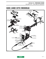
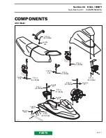
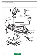

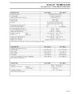

Section 04
HULL / BODY
Sub-Section 01
(COMPONENTS)
04-01-10
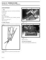
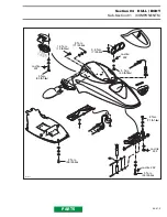
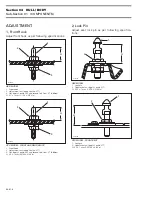
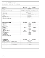
1. Nuts
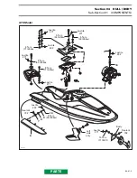
Using a heat gun, heat jet pump support until it is
possible to pull it.
NOTE :
Shims may have been installed be-
tween support and body. Do not remove
these shims, otherwise jet pump alignment will
be altered.
9, Shoe
Using a heat gun, heat shoe and pry it using a
piece of wood.
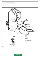
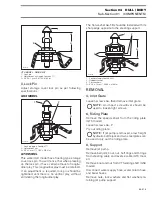
INSTALLATION
Installation is essentially the reverse of removal
procedures. However, pay particular attention to
the following.
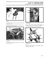
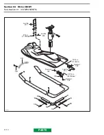
Follow the torquing sequence for the support
no.
8
and riding plate
no. 6
as shown in the next illus-
trations.
CAUTION : Apply all specified torques
and service products as per main illustra-
tions at the beginning of this sub-section.
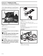
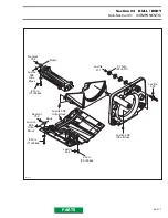
Apply Loctite 598 Ultra Black on the following
components as indicated by the shaded area in
the next illustrations. The seam of sealant should
be 10 mm (25/64 in) wide and 4 mm (5/32 in) high.
9, Shoe
8, Support
6, Riding Plate
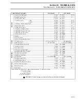
F07L0AA
1
'
-
F07L0BA
F07L0CA
3
2
1
4
F07L0DA
3
7 1
8 2
4
5
6


