


Section 02
PROPULSION SYSTEM
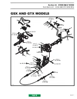
Sub-Section 01
(REVERSE SYSTEM)
02-01-2
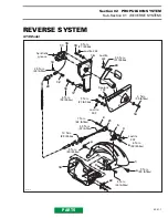
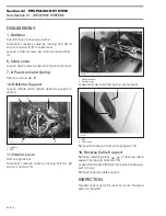
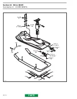
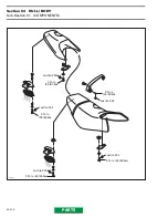
DISASSEMBLY
1, Deflector
Put shift lever in reverse position.
Disconnect reverse cable by loosing bolt
no. 2
and lock nut
no. 3
from cable lever.
Loosen 2 Allen screws
no. 4
and remove deflec-
tor.
5, Cable Lever
Loosen Allen screw
no. 6
and remove cable lever.
7, 8, Pawl Lock and Spring
Remove roll pin
no. 9
.
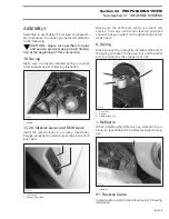
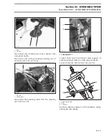
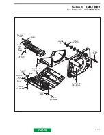
10, Deflector Support
Loosen 4 bolts which retains deflector support to
venturi.
1. Support
2. Bolt
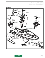
11, Interior Lever
Remove glove box.
Disconnect reverse cable by loosing bolt
no. 12
and lock nut
no. 13
.
1. Reverse cable
2. Interior lever
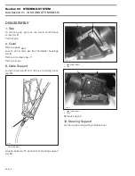
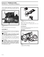
Loosen bolt
no. 14
retaining the interior lever.
1. Bolt
2. Shift lever
Remove the interior lever and spring
no. 15
.
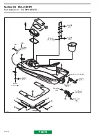
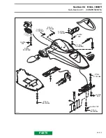
16, Reverse Cable Support
Remove retaining block
no. 17
of reverse cable
support by loosing bolts
no. 18
.
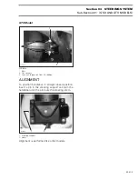
Loosen 3 bolts
no. 19
retaining reverse cable sup-
port to body.
Remove reverse cable support.
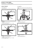
INSPECTION
Visually inspect parts for wear or cracks. Replace
parts as required.
F07J02A
1
2
2
2
2
F07J03A
1
2
F07J04A
1
2