


Section 04
HULL / BODY
Sub-Section 01
(COMPONENTS)
04-01-9
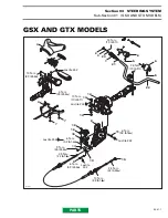
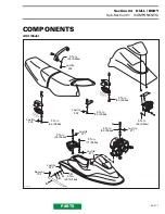
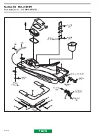
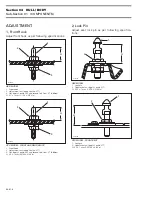
GTX MODEL - REAR SEAT
1. Lock pin
2. Adjustment nut (apply Loctite 271)
A. 33.5 ± 1 mm (1-5/16 ± 3/64 in)
3, Lock Pin
Adjust storage cover lock pin as per following
specifications :
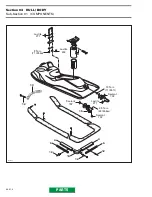
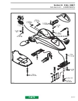
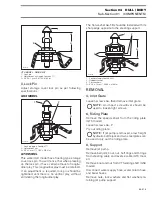
GSX MODEL
1. Lock pin (apply Loctite 271)
2. Adjustment nut
A. 34 ± 1 mm (1-11/32 ± 3/64 in)
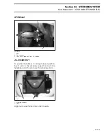
GTX MODEL
This watercraft model has a floating type storage
cover lock pin. You will notice that when pressing
on the lock pin, it has a certain amount of longitu-
dinal play. This longitudinal play must be retained.
If an adjustment is required, lock pin should be
tightened until there is no vertical play, without
eliminating the longitudinal play.
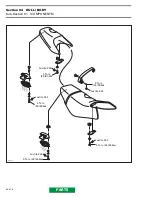
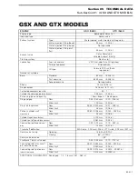
The flat washer
no. 10
should be installed with its
sharp edge opposite to the steering support.
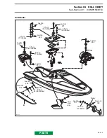
1. Lock pin (apply Loctite 242)
2. Rubber washer
3. Flat washers
A. 39.2 ± 1 mm (1-35/64 ± 3/64 in)
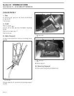
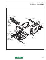
REMOVAL
4, Inlet Grate
Loosen screws
no. 5
and remove inlet grate.
NOTE :
An impact screwdriver should be
used to loosen tight screws.
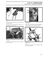
6, Riding Plate
Remove the speed sensor from the riding plate
(GTX model).
Loosen screws
no. 7
.
Pry out riding plate.
NOTE :
If jet pump is removed, a low height
hydraulic bottle jack and two steel plates can
be used to pry out the riding plate.
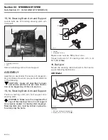
8, Support
Remove jet pump.
Remove ball joint, boot, nut, half rings and O-rings
from steering cable and reverse cable (GTX mod-
el).
Remove boot and nut from VTS sliding shaft (GSX
model).
Disconnect water supply hose, water return hose
and bailer hoses.
Remove nuts, lock washers and flat washers re-
taining jet pump support.
F06L03A
A
1
2
F06L04A
A
2
1
F07L09A
A
3
1
2
'
'


