
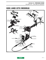

Section 03
STEERING SYSTEM
Sub-Section 01
(GSX AND GTX MODELS)
03-01-4
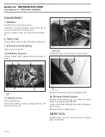
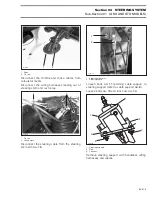
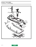
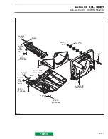
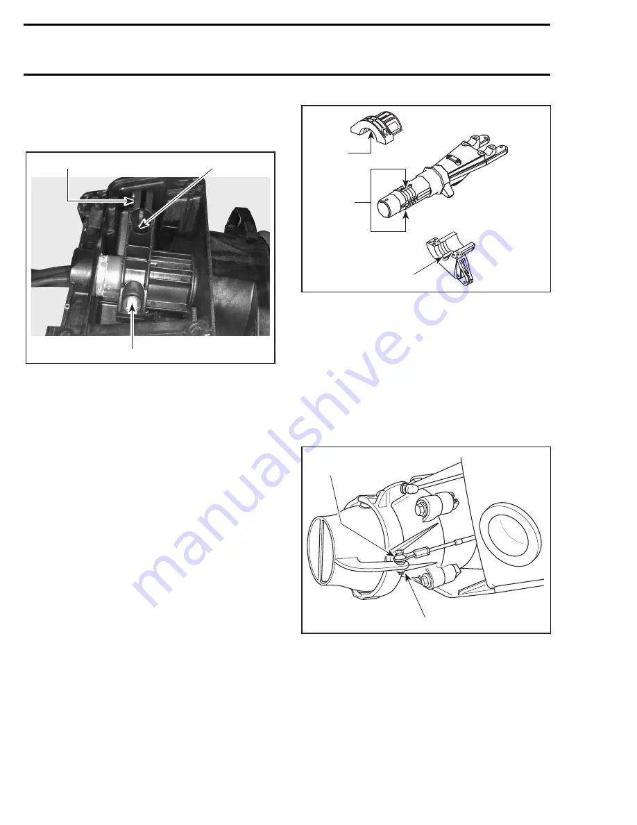
15, 16, Steering Stem Arm and Support
Loosen bolts
no. 17
retaining steering stem arm
to support.
1. Steering stem arm
2. Bolt
Remove steering stem arm and support.
ASSEMBLY
Assembly is essentially the reverse of disassem-
bly procedures. However, pay particular attention
to the following.
CAUTION : Apply all specified torques
and service products as per main illustra-
tion at the beginning of this sub-section.
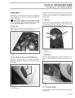
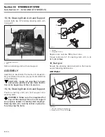
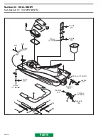
15, 16, Steering Stem Arm and Support
Position steering stem arm and support onto
steering stem.
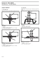
WARNING : Make sure the integrated flat
keys of the steering stem arm and support
are properly seated in steering stem keyways.
Steering stem arm must be locked in place be-
fore torquing the bolts.
1. Keyway
2. Integrated flat key
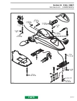
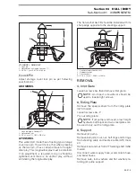
Replace lock nuts
no. 18
by new ones.
Torque bolts
no. 17
of steering stem arm to 6
N•m (53 lbf•
in
).
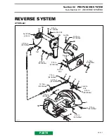
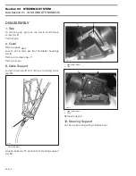
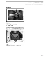
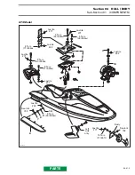
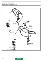
19, Ball joint
Secure the steering cable ball joint to the nozzle
as per following illustrations.
GSX Model
TYPICAL
1. Ball joint on top of steering arm
2. Torque nut to 7 N•m (62 lbf•
in
)
F07K08A
2
1
2
-
;
F07K09A
2
1
2
F01J58A
1
2