background image

03-72

SECTION 03 - ENGINE PREPARATION

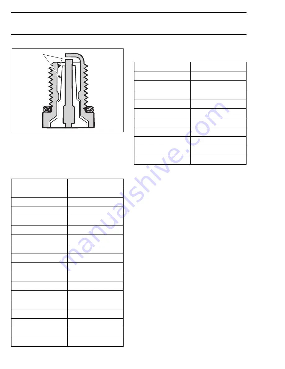
1. Location to check spark plug coloration

Refer to the appropriate 

Shop Manual of your wa-

tercraft for instructions on changing carburetor
jetting.

Main Jets for Mikuni Super BN 
Carburetors

Pilot Jets for Mikuni Super BN 
Carburetors

If in doubt with carburetion jetting, always begin
with a rich setting and work toward a lean adjust-
ment.

NOTE:

It is recommended you always race with

your fuel tank valve on the “reserve” position.
This should eliminate any possibility of air enter-
ing in the fuel system should the fuel tank level be
lower than a quarter full.

RACING ENGINE PREPARATION 
SUMMARY

NOTE:

Most machining and/or grinding is illegal in

limited class racing. Keep your watercraft legal:
check the rules.

1. Remove and disassemble the engine according

to appropriate model year 

Shop Manual proce-

dures.

2. With the crankshaft resting in the lower half of

the crankcase, set up a dial indicator and check
the runout of the crankshaft at both ends. You
should see no more than 0.05 mm (.002 in)
runout. If you have the capability, adjust the
crankshaft as close to perfect as possible.

MAIN JET SIZE

PART NUMBER

102.5

270 500 157

105

270 500 158

107.5

270 500 116

110

270 500 159

115

270 500 181

120

270 500 160

122.5

270 500 161

125

270 500 162

127.5

270 500 148

130

270 500 163

132.5

270 500 225

135

270 500 174

137.5

270 500 268

140

270 500 251

142.5

270 500 209

147.5

270 500 210

175

270 500 318

F01E1AA

1

PILOT JET SIZE

PART NUMBER

55

270 500 202

57.5

270 500 201

60

270 500 180

62.5

270 500 164

65

270 500 117

67.5

370 500 165

70

270 500 175

72.5

270 500 166

75

270 500 149

77.5

270 500 167

Summary of Contents for Bombardier

Page 1: ......

Page 2: ...a racer in all conditions KEEPING YOUR WATERCRAFT LEGAL IS YOUR RESPONSIBILITY Read and know your rule book WARNING This information relates to the preparation and use of watercraft in competitive events Bombar dier inc disclaims liability for all damages and or injuries resulting from the improper use of the contents We strongly recommend that these modifications be carried out and or verified by...

Page 3: ... to accomplish an adjustment or procedure outlined in your service manual please have your local authorized SEA DOO dealer perform the task The handbook also provides information on race day activities rider presentation general racing practic es sponsor solicitation and other useful tips to successful racing Some sea doo watercraft may need to be altered from their stock configuration even in the...

Page 4: ...LS 01 8 SPONSORSHIP AND SOLICITATION 01 9 THE PROFESSIONALS POINT OF VIEW 01 11 SECTION 02 HULL PREPARATION PREPARING THE HULL FOR INSPECTION 02 2 MEASURING THE HULL 02 2 TRUING THE HULL 02 2 PAINTING 02 3 CONCEPTTM PAINTING PROCEDURE 02 3 DELTATM PAINTING PROCEDURE 02 4 SEA DOO PAINT CODES 02 5 STORAGE COVER PAINT CODES 02 6 ENGINE PAINT CODES 02 6 EXHAUST SYSTEM PAINT CODES 02 6 MODELS WITH CORR...

Page 5: ... OCTANE REQUIREMENTS FOR ROTAX ENGINES 03 17 RAVE VALVE OPERATION 03 17 FUNCTION OF THE ROTARY VALVE INTAKE SYSTEM 03 20 ROTARY VALVE TIMING 03 25 ROTARY VALVE IDENTIFICATION 03 27 CYLINDER PORTING MAPS 03 29 ENGINE LEAKAGE TEST 03 33 ENGINE LEAKAGE DIAGNOSTIC FLOW CHART 03 38 CRANKSHAFT INSPECTION 03 39 ENGINE BREAK IN PROCEDURE 03 42 FUNCTION OF AN EXHAUST SYSTEM 03 43 WATER FLOW REGULATOR VALVE...

Page 6: ...PECIFICATIONS AND BOOT APPLICATIONS 04 9 IMPELLER PITCH CHART 04 10 ENGINE JET PUMP ALIGNMENT 04 11 FUNCTIONS OF THE VARIABLE TRIM SYSTEM VTS 04 12 PROPULSION SYSTEM MAINTENANCE 04 13 SECTION 05 MISCELLANEOUS EQUIVALENT WEIGHTS AND MEASURES CHART 05 2 GLOSSARY OF TERMS IN PERSONNAL WATERCRAFT RACING 05 3 RACER S LOG 05 4 AFTERMARKET MANUFACTURERS 05 5 USE AT YOUR OWN RISK 05 6 TABLE OF CONTENTS ...

Page 7: ...tten to help in the prepara tion of a Sea Doo watercraft for competitive events Carefully study the association rule book and class of racing you intend to compete in before making any modifications to your watercraft Your watercraft must conform to association specifica tions The IJSBA is the sanctioning association for the United States You can contact them at the ad dress listed below The IJSBA...

Page 8: ...TIES 01 2 PREPARING FOR A SAFETY INSPECTION 01 5 PRERACE MAINTENANCE 01 6 MAINTENANCE BETWEEN RACES 01 7 EQUIPMENT AND SPARE PARTS TO BRING TO THE RACE 01 7 PIT AREA PRESENTATION 01 7 INTERACTION WITH RACE OFFICIALS 01 8 SPONSORSHIP AND SOLICITATION 01 9 THE PROFESSIONALS POINT OF VIEW 01 11 ...

Page 9: ...r line your equipment and tent if you have one must be placed little further away The promoter may not be on hand during your setup Look the site over the night before if possible talk to the promoter to find out where to set up by doing this you will avoid moving all your equip ment later and you will be able to get a choice spot with easy access to the water as well as to your equipment You are ...

Page 10: ...ll line you up randomly as post ed on the pit board 3 You will be lined up in order of your finish posi tion from your previous qualifier or heat race 9 Starting Once in position on the line you will be allowed 1 or 2 holders to keep your boat in position safely The holders will hold back your boat while the en gine is running just before the rubber band is snapped It is important that you practic...

Page 11: ...r your hull number is recorded the inspector may make a series of visual inspections inside and outside the hull to verify class legality or to see if safety requirements have been met The inspec tor may use a paint type seal on various areas of the engine to prevent a rider from going into the engine and removing illegal parts that may have been used for qualifying If after the race some thing go...

Page 12: ...rs will be assigned to you by the IJSBA or in regional events you will be allowed to choose your own number providing the number has not already been select ed by another rider Check with the IJSBA or your regional promoter prior to buying or painting num bers on your boat 2 If your watercraft model is not equipped with a flush bow eyelet it must be removed prior to inspection and racing It is req...

Page 13: ...mp is being used 6 Check the fuel filter for debris or water if any abnormality is noticed remove and clean the fuel tank fuel filter fuel lines and carburetors 7 Carburetor diaphragm screws should be checked and pop off pressure verified Now is a good time to check your low and high speed fuel mixture screws to make sure they have not backed out and are still set to the required setting Throttle ...

Page 14: ...fied for an event the backup boat is used If the boat has already been qualified for a race the parts are taken from the backup boat then used to repair the qualified boat These racers normally bring extra parts as well All racers should be equipped with the Shop Man ual for their watercraft They should have at mini mum the necessary tools to accomplish the service procedures that they are capable...

Page 15: ...your pit area clean bring a small waste can for your pit it s another place to put decals it adds to the professional look You are required to have a fire extinguisher in your pit Do not set it on the ground it will be hard to locate in the event of an emergency Attach a hanger to one tent post and place the extinguisher on it Your fuel contain er should be of high quality red in color a require m...

Page 16: ... no error is found the Scorer can explain to you how they arrived at the decision If your complaint concerns the legality of a given watercraft s modification go to the Technical In spector The Inspector knows the modification rules better than any other official it s their job If you believe that a boat is illegal tell the Inspector If the item can be visually inspected without any tear down the ...

Page 17: ...er your statement of goals list all the races you have competed in complete with your finishing positions and overall titles Conclude your resume with a listing of your previous sponsors their product line and any major media coverage that you have received that would be advantageous for a sponsor to know The complexity of your sponsorship proposal will vary quite noticeably depending upon the lev...

Page 18: ...s is a team effort Next a successful rider always has inner drive This is required to push through those tough times A DNF a lapped rider or a bad start can break even the strongest spirit but having a strong will to perceiver and overcome is needed to rebound in the event that luck isn t always look ing your way Additionally focus is also a key We look for riders who have started at a given point...

Page 19: ...age to improve my endurance and cornering skills This type of conditioning has taught me dedication motivation responsibility and self con trol The lessons I have learned have helped me sharpen the skills I need to be a competitive racer Racing may not be for everyone because of the commitment involved But for me I feel racing brings out the best in me and builds physical en durance I knew at my f...

Page 20: ... 02 3 CONCEPTTM PAINTING PROCEDURE 02 3 DELTATM PAINTING PROCEDURE 02 4 SEA DOO PAINT CODES 02 5 STORAGE COVER PAINT CODES 02 6 ENGINE PAINT CODES 02 6 EXHAUST SYSTEM PAINT CODES 02 6 MODELS WITH CORRESPONDING BODY HULL PAINT CODES 02 6 SEALING OF BODY COMPONENTS 02 8 HULL AND BODY MAINTENANCE TIPS 02 8 LIGHTWEIGHT PARTS 02 8 SPONSON KITS 02 8 ...

Page 21: ...st rigid side along the bot tom of the hull Identify the low and high spots on the surface as shown below 1 Place straight edge at different locations as shown by shadow areas 2 Not necessary to true beyond this point TRUING THE HULL Truing the hull means to make the hull as straight as possible This will help you gain maximum per formance and top speed Follow these steps and you will attain a goo...

Page 22: ... painting practices Primer DP Epoxy Primer DP 401 Catalyst DX 1791 1792 prime before topcoating Primer Surfacer K36 K201 K200 K201 or DZ KONDAR Primer Surfacers NOTE KONDAR must be sealed before apply ing CONCEPT color Sealer KTS30 2K Sealer DP Epoxy Primer reduced as a sealer or DAS 1980 or DAS 1987 Direct Gloss Color How to Mix Standard Air Dry Mix CONCEPT Color 2 1 1 2 parts color with 1 part D...

Page 23: ...ELTATM Polyurethane Color Apply the first coat at 1 5 1 8 wet mils Allow a minimum of 15 minutes flash time prior to application of the second coat Apply a second coat of DELTATM using the same technique as the first application paying strict attention to gun set up and proper equipment choices Recommended Spray Equipment Dry Time at 21 C 70 F dust free 25 35 minutes tack free 2 1 2 3 hours tape s...

Page 24: ... 1997 98260 293 500 082 5801 88 02 YELLOW 1988 1989 88207 293 500 008 5801 88 03 DARK GRAY 38248 5801 88 04 BLACK 9551 5803 90 01 YELLOW 1990 1991 88207 293 500 008 5803 90 02 BLUE 17862 293 500 014 5804 91 01 BLUE 17861 293 500 073 5804 91 03 PURPLE 59962 293 500 042 5804 92 02 LAVENDER DFM 88761 59974 293 500 059 5805 92 01 GRAY 38269 293 500 009 5806 93 01 LIGHT GRAY 38287 293 500 067 5806 93 0...

Page 25: ...7 Model Number Body Hull Bombardier Paint Code SP 5879 5801 88 01 SPX 5834 5661 5801 88 01 M 506 GS 5621 5801 88 01 GSI 5622 5801 88 01 GSX 5625 5801 88 01 B 176 GSX LTD 5625 M 519 B 176 XP 5662 M 506 GTS 5818 5801 88 01 GTI 5641 5801 88 01 GTX 5642 5801 88 01 M 512 HX 5882 5801 88 01 M 506 Model Name 1996 Model Number Body Hull Bombardier Paint Code SP 5876 5801 88 01 SPX 5877 5801 88 01 M 511 SP...

Page 26: ...8 01 GTX 5861 5801 88 01 Model Name 1992 Model Number Body Hull Bombardier Paint Code SP 5805 5801 88 01 5810 90 02 XP 5851 5801 88 01 5804 91 01 GTS 5812 5801 88 01 GTX 5860 5801 88 01 Model Name 1991 Model Number Body Hull Bombardier Paint Code SP 5804 5801 88 01 5810 90 02 XP 5850 5801 88 01 5804 91 01 GT 5811 5801 88 01 5810 90 02 Model Name 1990 Model Number Body Hull Bombardier Paint Code SP...

Page 27: ...s Short V shaped Sponsons Long Sponsons Installation Guidelines The following pertain to all types of sponsons The sponson holes location are given for short type For long type it is recommended to experiment to obtain what you require Minor adjustments in angle or height location of the sponson can have a tremendous effect on handling and speed The position illustrated is a good starting point Pr...

Page 28: ...1 4 in steel rod through the urethane foam by hand From inside bilge attach the hole saw to the steel rod Refer to the following illustration 1 Urethane foam Start cutting the urethane foam by carefully pull ing hole saw into the foam and operating the drill in reverse position NOTE Depending on hole saw depth approxi mately 3 passes will be required to cut the ure thane foam Keep the first foam c...

Page 29: ...aw pick up tool or a 10 mm deep socket Torque nuts to 14 N m 10 lbf ft Urethane Foam Reinstallation When sponsons installation is completed you can reinstall the first removed urethane foam core into each hole Glue with 732 multi purpose seal ant P N 293 800 006 F01P09A ...

Page 30: ...HAMBER VOLUME 03 17 OCTANE REQUIREMENTS FOR ROTAX ENGINES 03 17 RAVE VALVE OPERATION 03 17 FUNCTION OF THE ROTARY VALVE INTAKE SYSTEM 03 20 ROTARY VALVE TIMING 03 25 ROTARY VALVE IDENTIFICATION 03 27 CYLINDER PORTING MAPS 03 29 ENGINE LEAKAGE TEST 03 33 ENGINE LEAKAGE DIAGNOSTIC FLOW CHART 03 38 CRANKSHAFT INSPECTION 03 39 ENGINE BREAK IN PROCEDURE 03 42 FUNCTION OF AN EXHAUST SYSTEM 03 43 WATER F...

Page 31: ...rom stan dard timing specifications to achieve maximum power output if modifications are made to the en gine BASIC ENGINE TERMINOLOGY MODEL YEAR SHOP MANUAL PART NUMBER 1989 295 000 060 1990 219 100 002 1991 219 100 004 1992 219 100 006 1993 219 100 008 1994 219 100 010 1995 219 100 013 1996 219 100 031 1997 219 100 048 Cycle In a combustion engine a cycle is accomplished when the 4 phases intake ...

Page 32: ...nder 3 Cylinder head 4 Cylinder head cover 5 Spark plug 6 Combustion chamber 7 Exhaust port 8 Transfer port 9 Wrist pin 10 Rotary valve 11 Intake port 12 Oil injection pump 13 Crankcase 14 Crankshaft 15 Connecting rod 16 Piston F01D5DS 8 7 6 5 4 3 2 1 16 15 14 13 12 11 10 9 ...

Page 33: ... com bustion chamber A large hole bored through it ac cepts a piston Through the years Rotax engineers have designed many types of cylinder blocks to attain better engine efficiency TWO CYLINDERS SHOWN Piston A shaped cast aluminum alloy plug made to fit inside the cylinder bore It is attached to the crank shaft by a connecting rod and wrist pin PISTON SHOWN The piston serves 3 purposes 1 Transmit...

Page 34: ...he port edges and piston ring breakage would occur When installing a new piston and or piston rings it is critically important that piston ring locat ing pin is matched or indexed with gap in piston ring This should be checked as the cylinders are being installed 1 Locating pin Two types of compression rings are used with Ro tax pistons 1 rectangular cast iron 2 L type trapezoid molybdenum RECTANG...

Page 35: ...reciprocating movement of the piston into rotary movement The crankshaft is supported by ball bearings mounted inside the crankcase It is finely ma chined to obtain precision journals and perfect alignment Distortion or out of round will impair the necessary free and smooth rotation Connecting Rod The connecting rod links the piston to the crank shaft Within each bored end of the rod is a needle b...

Page 36: ...ankcase and cylinder areas Transfer Ports To achieve greater efficiency Rotax engineers have designed the engines with 2 extra transfer ports An engine with 4 transfer ports enhances the rap id escape of the air fuel mixture from the crank case into the combustion chamber 1 Transfer ports 2 Intake port The configuration of the transfer ports is termed as being tangential type flow In other words t...

Page 37: ...ad of com pleting the cycle in 4 stroke or 720 crankshaft ro tation the 2 stroke engine completes the cycle in only 360 2 stroke In other words the 2 stroke engine piston travels to Top Dead Center and back to Bottom Dead Center once to complete the intake compression combustion and exhaust phases NOTE On all Sea Doo engines except the 947 the intake is controlled by a rotary valve On the 947 engi...

Page 38: ...s are allowed to escape 1 Exhaust 2 Burnt gases 3 Intake 4 Fresh charge 4 Transfer Port Condition Intake port Closed Exhaust port Opened Transfer port Opened Boost port Opened Near the bottom of the downward stroke the transfer port is uncovered and the compressed air fuel mixture inside the crankcase rushes into the cylinder and combustion chamber Just after the opening of the transfer port the b...

Page 39: ...h the firing of the spark plug This initial process generates heat and pressure which in turn is transmitted by conduction to the contiguous portion of the unburned mixture When this portion has reached the point of self ignition it starts to burn releasing more pressure and heat This burning action called a flame front travels at a speed of approximately 30 m 100 ft per second until all mixture i...

Page 40: ...mber These shock waves can sometimes be heard as pinging this pinging is especially detrimental to engines with raised compression ratios While these shock waves can be detrimental to the me chanical integrity of the engine it is the genera tion of excessive heat that causes most problems in 2 stroke For many various reasons the piston may expand excessively causing a seizure or the piston dome ma...

Page 41: ... damage or complete failure may occur if this con dition is allowed to continue These 2 conditions can be heard if you are listening carefully The en gine will produce a sound similar to glass bottles rattling together or a noise which sounds like transmission gears growling These sounds will usually be more audible at specific throttle posi tions Do not hold the throttle at these positions for an...

Page 42: ...g combustion chamber SQUISH AREA Rotax cylinder heads incorporate a squish area This area is basically a ledge projecting beyond combustion chamber area In operation as the piston ascends and approaches the ledge a rapid squeezing action is applied to the air fuel mixture contained in the area immediately between the piston dome and the ledge This squishing action forces the entrapped mixture rapi...

Page 43: ... 055 in engine type 657 1 00 mm 1 60 mm 039 in 063 in engine type 717 1 00 mm 1 60 mm 039 in 063 in engine type 787 COMBUSTION CHAMBER VOLUME MEASUREMENT The combustion chamber volume is the region in the cylinder head above the piston at Top Dead Center It is measured with the cylinder head in stalled on the engine 1 Combustion chamber NOTE When checking the combustion chamber volume engine must ...

Page 44: ...g hole NOTE The liquid level in cylinder must not de crease after filling If so there is a leak between piston and cylinder The recorded volume would be false 5 Let burette stand upward for about 10 min un til liquid level is stabilized 6 Read the burette scale to obtain the quantity of liquid injected in the combustion chamber Record the volume which we will note as V2 NOTE When the combustion ch...

Page 45: ...rected Compression Ratio of Production Engines 11 5 1 engine type 587 12 2 1 engine type 657 12 25 1 engine type 717 11 25 1 engine type 787 11 75 1 engine type 947 Corrected Compression Ratio In a 2 cycle engine a portion of the stroke is opened to the atmosphere via the exhaust port The corrected compression ratio is calculated as the piston closes the exhaust port C C R WHERE C C R Corrected Co...

Page 46: ...tane fuel if the compression ratio is not higher than pro duction However if the compression ratio is higher it may become necessary to use a higher octane fuel or engine damage will result Do not use a compression gauge to determine compres sion ratio A compression pressure test is useful in checking general condition of any engine but is useless when checking compression ratio Minimum octane req...

Page 47: ...exhaust port allow ex haust gas pressure to reach the diaphragm To the outside of the return spring is a red plastic adjustment knob Turning the adjustment in or out changes the preload on the return spring which in turn will change the RPM at which the RAVE valve opens and closes 1 Sliding valve 2 Diaphragm 3 Spring 4 Exhaust port 5 Adjustment knob As the throttle is opened and the engine begins ...

Page 48: ...urve 2 This transition takes place very rapidly at full throttle and from a practical stand point can be considered to be instantaneous at item 7 Gradual application of the throttle howev er will result in the RAVE valve opening much later If the RAVE valve opens toos late the engine will bog or hesitate momentarily as the RPM increas es Full peak performance item 6 is still available From a funct...

Page 49: ...ly with regard to piston position Example 130 BTDC opening 65 ATDC closing While also allowing for an un obstructed intake tract to provide maximum air flow into the engine This is best accomplished by using a rotary valve type inlet The rotary valve engine is one of the most innova tive concepts to be applied to 2 stroke watercraft engines Simply stated the design produces more horse power out of...

Page 50: ...e bottom of the downward stroke the transfer ports are uncovered by the piston and the compressed air fuel mixture in the crankcase rushes into the combustion chamber via the transfer ports Piston dome and combustion chamber configuration and exhaust back pres sures prevent fresh charge air fuel mixture from escaping through the exhaust port This also as sists in clearing the combustion chamber of...

Page 51: ...er to avoid fresh charge spitback With the rotary valve duration of the intake is asymmetrical In piston port engines intake dura tion is symmetrical With the central rotary valve complete control of intake timing means greater torque at lower RPM s more peak power and easier starting Some modern engines such as the 947 use reed valves in the crankcase to increase overall perfor mance over piston ...

Page 52: ...here is two methods to verify rotary valve cover clearance One with a 45 feeler gauge the other one with a solder 45 Feeler Gauge Method Remove O ring from rotary valve cover Remove intake manifold from rotary valve cover except 787 engine Reinstall cover in place WITHOUT its O ring and torque screws to 20 N m 15 lbf ft Feeler gauge blade from 0 25 mm 010 in to 0 35 mm 014 in thickness should fit ...

Page 53: ...NG GROOVE BASE 1 Cover seating surface 2 O ring groove depth must be 1 0 0 03 mm 039 001 in Reverify the clearance At assembly the rotary valve timing must remain as per original setting NOTE If rotary valve crankcase surface is worn it is possible to have it reworked at the factory Contact your dealer or distributor Crankshaft and Rotary Valve Shaft Drive Gears Backlash Remove PTO flywheel guard ...

Page 54: ...ee wheel and mark here NOTE Do not rotate the crankshaft For closing mark first align 360 line of degree wheel with TOP of MAG side inlet port Then find 65 line on degree wheel and mark crankcase at this point CLOSING MARK Step Top of MAG inlet port Align 360 line of degree wheel Step Find 65 on degree wheel and mark here Remove degree wheel CAUTION Never use the ridge molded in crankcase as a tim...

Page 55: ...it with the drive gear in a different po sition with respect to the crankshaft gear and or valve shaft splines a different valve position may be established When a crankshaft rotary valve shaft or drive gear is removed or replaced it will be necessary to reverify the timing Apply Sea Doo injection oil on rotary valve surfac es before reassembling rotary valve cover Remove TDC gauge Rotary Valve Co...

Page 56: ...03 27 SECTION 03 ENGINE PREPARATION ROTARY VALVE IDENTIFICATION 290 924 508 actual size 147 cut out angle A00A0YS TEMPLATE ...

Page 57: ...03 28 SECTION 03 ENGINE PREPARATION F01D8SS 159 cut out angle TEMPLATE 290 924 502 actual size 159 cut out angle 132 cut out angle 290 924 504 actual size ...

Page 58: ...ION 03 ENGINE PREPARATION CYLINDER PORTING MAPS NOTE See tables on next pages for porting map specifications Refer to the following illustration for measurement references E1 E1 E2 E3 T1 T2 T3 T4 B1 B2 B3 F01D7CS ...

Page 59: ... length bottom to top B3 91 5 mm 97 5 mm Main transfer height T1 T2 50 5 mm 51 0 mm 54 0 mm 54 0 mm Bottom width of main transfers T3 T4 26 0 mm 21 0 mm 26 0 mm 21 0 mm Total cylinder height 109 5 mm 113 5 mm Exhaust outlet width at Y pipe 49 0 mm 53 0 mm Exhaust outlet height at Y pipe 32 0 mm 33 0 mm Squish band clearance 1 5 mm 1 1 mm Cylinder head volume without piston 40 8 cc 42 2 cc Combusti...

Page 60: ...48 1 mm 54 3 mm 54 3 mm 54 3 mm 54 3 mm 53 6 mm 53 9 mm 58 2 mm 58 6 mm Bottom width of main transfer T3 T4 24 1 mm 21 9 mm 24 2 mm 22 3 mm 24 2 mm 22 3 mm 26 5 mm 24 5 mm 28 5 mm 26 5 mm Total cylinder height 109 4 mm 113 4 mm 113 4 mm 117 8 mm 122 5 mm Exhaust outlet width at Y pipe 49 0 mm 53 0 mm 53 0 mm 53 0 mm 56 0 mm Exhaust outlet height at Y pipe 32 0 mm 33 0 mm 33 0 mm 33 0 mm 36 0 mm Sq...

Page 61: ...fer height T1 T2 49 5 mm 49 5 mm 51 8 mm 51 8 mm 56 7 mm 56 7 mm 61 20 mm 61 10 mm Main transfer width at bottom T3 T4 20 0 mm 21 0 mm 25 0 mm 20 0 mm 28 7 mm 22 8 mm 30 60 mm 29 80 mm Total cylinder height 109 6 mm 114 3 mm 122 0 mm 124 50 mm Exhaust outlet height at Y type 49 0 mm 53 0 mm 56 0 mm 64 40 mm Exhaust outlet width at Y type 32 0 mm 33 0 mm 36 0 mm 37 70 mm Squish band clearance 1 5 m...

Page 62: ...ensure a prop er sealing When pressurizing the engine first confirm that the components of the Engine Leak Test Kit are not leaking by spraying a solution of soapy water on all hoses connections fittings plates etc If there is a leak bubbles will indicate leak location Three areas of the engine will be tested in se quence as per the diagnostic flow chart on page 03 38 1 Engine Cooling System 2 Bot...

Page 63: ... with a screw 3 Block engine drain hose with a hose pincher 4 Use 2 washers with exhaust manifold stud NOTE Water is not required for testing Activate pump and pressurize engine cooling sys tem to 34 kPa 5 PSI Wait 3 minutes and check if pressure drops if so verify all testing components If kit components are not leaking and pressure drops verify all external jointed surfaces tem perature sensor a...

Page 64: ...en adequately NOTE On engines with the RAVE system the boot and O ring can be checked for leakage with the valve in place Simply remove the cover to ex pose the boot Make sure the spark plugs are installed and tight en Block pulse hose using a hose pincher NOTE Do not block the rotary valve shaft hoses Install pump to the exhaust plate fitting 587 ENGINE 1 Intake plate 2 Plug pulse hose with a pin...

Page 65: ...te a defective check valve If the above mentioned components are not leak ing block both oil hoses of the rotary valve shaft using hose pinchers NOTE If leakage stops at this point proceed with Rotary Valve Shaft testing If there is still some leakage remove the PTO fly wheel to verify outer seal If no leak is found on the PTO side outer seal re move magneto flywheel and verify crankshaft outer se...

Page 66: ...es a defective PTO side crankshaft inner seal Remove MAG side spark plug If pressure drops it indicates a defective MAG side crankshaft inner seal If the above mentioned components are not leak ing and there is a pressure drops remove the ro tary valve cover Check the seal of the rotary valve shaft If the rotary valve shaft is not leaking it could indi cates a defective engine casting Disassemble ...

Page 67: ...ECK SEAL OF ROTARY VALVE SHAFT IS SEAL LEAKING CAREFULLY INSPECT ENGINE CASTINGS PARTICULARLY THE THREADED HOLE AREAS YES YES NO PRESSURIZE ENGINE COOLING SYSTEM IS SYSTEM LEAKING CHECK TESTING KIT REPLACE O RING OF CYLINDER HEAD AND OR CYLINDER BASE GASKET YES YES NO CHECK TESTING KIT IS RESERVOIR LEAKING PRESSURIZE ROTARY VALVE GEAR RESERVOIR IN CRANKCASE REPLACE GASKET OR O RING RE SEAL LEAKING...

Page 68: ...t pro ceed as follows Remove magneto housing cover Remove MAG flywheel nut and also the mag neto rotor for the 787 engine Install Bombardier degree wheel P N 295 000 007 on crankshaft end Hand tighten nut only Remove both spark plugs Install a TDC gauge P N 295 000 143 in spark plug hole on MAG cylinder side Bring MAG piston at Top Dead Center As a needle pointer secure a wire with a cover screw a...

Page 69: ...aft and or components are found worn or damaged it must be replaced or repaired by a shop specializing in this type of work The inspection of engine crankshaft should in clude the following measurements Connecting Rod Straightness Align a steel ruler on edge of small end connect ing rod bore Check if ruler is perfectly aligned with edge of big end 1 Ruler must be aligned with edge of connecting ro...

Page 70: ...re distance between thrust washer and crankshaft counterweight 1 Measuring big end axial play 2 Feeler gauge At Assembly Pay particular attention to the following Bearing Apply Loctite 767 anti seize lubricant P N 293 550 001 on bearing seats Prior to installation place bearings into a container filled with oil previously heated to 75 C 167 F This will expand bearings and ease installation Cranksh...

Page 71: ...rer rec ommendation is about 10 operating hours During this period maximum throttle should not exceed 3 4 however brief full acceleration and speed variations contribute to a good break in Continued wide open throttle accelerations pro longed cruising speeds and overloading the en gine are detrimental during the break in period To assure additional protection during the initial engine break in 250...

Page 72: ... initiated as exhaust port opens 2 Tailpipe or stinger 3 Head pipe 4 Diverging cone 5 Mid section 6 Converging cone This wave travels down the header pipe and ex pands into the diverging cone causing a negative pressure of about 48 kPa 7 PSI This negative pressure helps pull the remaining exhaust particles out of the cylinder It also helps pull the fresh charge up the transfer ports and into the c...

Page 73: ...ufacturer of the pipe to determine if the pipe is race legal by your race sanctioning body IJSBA Some pipes will fit your craft but may not be race legal because of inadequate head pipe cooling or mounting of the pipe requires relocation of the muf fler Muffler relocation is illegal by several sanction ing bodies for Limited Class racing WATER FLOW REGULATOR VALVE All watercraft equipped with a 78...

Page 74: ...d to supply water to the now discarded water regulator At tach a 1 4 in T fitting to the hose in place of the water flow regulator valve Attach 2 hoses of 1 4 in hoses to the T fitting run 1 hose to the new fit ting on the muffler which replaces the water flow regulator valve and 1 hose to the fitting on the tuned head pipe 4 Start the hard jetting procedure by installing a no 200 Mikuni main jet ...

Page 75: ... fitting 3 New fitting threaded to accept a Mikuni jet size 200 IMPORTANT It is necessary to readjust the exhaust hard jetting for maximum performance when racing in different water temperatures Because of this it is recommended that you keep a record of the jet sizes chosen at given water temperatures 1 F01E23S 2 3 ...

Page 76: ... The cylinder head cooling jacket has been divided into 2 sections One side of the head s water jacket exhaust side has cool incoming water circulate around the combustion chambers then into the tuned pipe and exhaust manifold cooling jacket The preheated water then enters the cooling jack ets of the cylinders From the cylinders the water flows upward through calculated holes to the out let side o...

Page 77: ...eam of water flows out of bleed outlets located near stern eyelet Calibrated outlet fittings limit water flow Pressure zone Lowest point of circuit allows draining whenever engine is stopped Water injected directly into exhaust gas for noise reduction and performance improvement Fresh water flows through tuned pipe and manifold water jackets Uppermost point of engine cylinder head cover allows ble...

Page 78: ...s located near stern eyelet 8 Calibrated outlet fittings limit water flow 9 Pressure zone 10 Engine water inlet hose 11 Tuned pipe bleed hose injects water into muffler to cool exhaust components GTX model 12 Lowest point of circuit allows draining whenever engine is stopped 13 Water injected directly into exhaust gas for noise reduction and performance improvement 14 Fresh water flows through tun...

Page 79: ...l stream of water flows out of bleed outlet located near stern eyelet Calibrated outlet fittings limit water flow Pressure zone Tuned pipe bleed hose injects water into muffler to cool exhaust components Lowest point of circuit allows draining whenever engine is stopped Water injected directly into exhaust gas for noise reduction and performance improvement Water flows through tuned pipe and manif...

Page 80: ... exceeds 96 99 C 205 210 F Calibrated cylinder head limits water flow Water flows through tuned pipe and manifold water jackets Water regulated by the water flow regulator valve and injected directly into exhaust gas for noise reduction and performance improvement Lowest point of circuit allows draining whenever engine is stopped Water inlet hose of valve Water directly injected into muffler to co...

Page 81: ...m the MPEM to high voltage current for the spark plugs All Systems Maximum power from a given engine configura tion is produced when peak combustion chamber pressure about 750 PSI takes place at about 15 after crankshaft rotation ATDC Normal combus tion is the controlled burning of the air fuel mix ture in the cylinder The flame is initiated at the spark plug and spreads to the unburned at the edg...

Page 82: ... the PTO flywheel 180 apart The ignition fires every 180 of crankshaft rotation at TDC and BDC so the marks should line up exactly when viewed with a timing light If they do not line up exactly and the crankshaft is correctly phased the flywheel magnets may not be phased exactly 180 apart Before checking ignition timing with a strobo scopic timing light dynamic test it is mandatory to scribe a tim...

Page 83: ...ng the engine to the rear engine mount Reinstall screw with timing mark pointer tool 1 Timing mark pointer tool P N 295 000 135 All Engines 4 Install and adjust a TDC gauge in MAG side spark plug hole TYPICAL 1 TDC gauge P N 295 000 143 on MAG side 5 Rotate PTO flywheel counterclockwise when facing it until piston is at Top Dead Center TYPICAL 1 Adjust gauge dial at zero 6 From this point rotate f...

Page 84: ...900 587 657 657X 717D and 717 Engines NOTE To perform this procedure make sure to use a stroboscopic timing light rated up to 6000 RPM Otherwise an inaccurate reading will be ob tained The ignition components are affected by temper ature variation therefore timing must be checked when engine is cold after idling for a MAXIMUM of 20 seconds 1 Connect an induction type tachometer P N 295 000 100 to ...

Page 85: ... If timing mark aligns with tool slot timing is prop erly set If not refer to Ignition Timing Adjust ment 787 787X and 947 Engines 1 Connect an induction type tachometer P N 295 000 100 to spark plug wire 1 Tachometer pick up 2 Connect timing light pick up to MAG side spark plug wire 1 Timing light pick up 3 Rev the engine to 3500 RPM and point beam of timing light straight in line with timing mar...

Page 86: ...ing is performed by moving armature plate clockwise to retard spark occurrence or counter clockwise to advance TYPICAL 1 To retard 2 To advance To adjust loosen 3 armature plate retaining screws and slightly rotate armature plate in prop er direction NOTE As a guideline turn the armature plate the same amount needed to align mark on PTO fly wheel TYPICAL 1 Retaining screw Example 1 When PTO flywhe...

Page 87: ...etarded up to 4 The timing mark refer to the physical component position when the spark must occur The MPEM must be synchronized with the mark For in stance on a particular engine the timing correc tion may need to be advanced to 2 so that the mark aligns with timing mark pointer tool This is not the real spark advance just a correction for the tolerances of the mechanical components Knowing that ...

Page 88: ...rt number 4 returns a correction of 1 advanced and this is not enough in this case You estimate the correction should be set to 2 advanced to align flywheel mark Back in the chart look to find 2 advanced This gives number 3 Enter this number with the programmer You recheck the timing with the timing light and if the mark is aligned the ignition timing is properly set Proceed as follows to adjust t...

Page 89: ...cold type plug has a relatively short insulator nose and transfers heat very rapidly into the cylin der head Such a plug is used in heavy duty or continuous high speed operation to avoid overheating The hot type plug has a longer insulator nose and transfers heat more slowly away from its firing end It runs hotter and burns off combustion de posits which might tend to foul the plug during prolonge...

Page 90: ...mm 10 mm 12 mm 8 mm 12 mm x 19 mm Reach A B C D E J Special Design Single Ground Special Alloy Dual Ground Special Alloy Racing Type Racing Version of V Type Half Heat Range Standard Center Electrode Fine Wire Center Electrode Booster Gap V Grooved Center Electrode A GV B C G L S V X Y Blank 18 mm ø 12 mm 31 64 14 mm ø 9 5 mm 3 8 F02H0MS Compact Type Projected Insulator Type Resistor Type Surface ...

Page 91: ...ndations as there were sources With this information we will be able to provide a reliable and consistent source of approved technical details Carburetor Installation MIKUNI SUPER BN38 DUAL CARBURETOR SET FOR HIGH PERFORMANCE APPLICATIONS NOTE As when installing any performance prod uct a degree of mechanical ability is required If after reviewing the parts and instructions you do not feel that yo...

Page 92: ...drawing see next page appears somewhat straight forward but some in teresting things appear as you study it Follow the fuel flow through the low speed circuit Fuel flows through the low speed jet and then is divided with part of the fuel being metered by the low speed screw An additional route the low speed fuel takes is through the by pass holes transition circuit Fuel is drawn through the by pas...

Page 93: ...ressures with spring pressure and needle valve combinations NOTE It is important to NOT select a needle valve that is too small for your application due to the fact that the needle valve can be a limiting fac tor in maximum fuel flow In other words in some applications engines require more fuel than small needle valves can deliver The needle valve sizes in Mikuni special set carbs have been carefu...

Page 94: ... 2 BN38I 37 17 BN38I 37 18 1 2 BN38I 37 25 BN38I 37 26 1 5 BN40I 38 9 BN40I 38 10 1 5 BN40I 38 15 1 5 BN40I 38 11 BN40I 38 12 2 0 BN38I 37BI 2 0 BN38 34 45B 2 0 BN38 34 58 BN38 34 59 2 0 BN 38 34 64 BN 38 34 65 2 0 BN38 34 73 BN38 34 74 2 0 BN38 34 92 BN38 34 93 2 0 BN38 34 110 BN38 34 111 2 0 BN38 34 147 2 0 BN46I 42 2 BN46I 42 3 ...

Page 95: ... Pump diaphragm 8 Filter 9 Restricter 10 Fuel return 11 Inner venturi 12 High speed screw 13 Main jet 14 Anti siphon valve 15 Pilot jet 16 Needle valve assembly 17 Regulator diaphragm 18 Arm 19 Arm spring 20 Fuel chamber 21 Vent to atmosphere 22 Low speed screw 3 2 1 22 21 20 19 18 17 16 15 14 13 12 11 10 9 8 7 6 5 4 F01F2CS ...

Page 96: ... jet 11 Check valve assembly 12 Choke valve 13 O ring 14 High speed screw 15 Idle speed screw 16 Pump cover 17 Gasket 18 Diaphragm 19 Diaphragm 20 Screw 2 per carb 21 Lock washer F01F05S Loctite 242 6 14 Loctite 242 20 21 20 N m 15 lbf ft MAG 13 Loctite 242 7 15 Anti seize lubricant 19 5 4 18 17 16 PTO Synthetic grease Synthetic grease 2 13 1 8 10 9 11 3 12 ...

Page 97: ...ine s lower RPM range Hopefully the porting is good and will in crease air flow at higher RPM s for better carbure tor response and increased power Freer Exhaust Systems Freer exhaust systems decrease suction Even though they flow more freely they reduce mani fold pressure within the carb Manifold pressure is a way of measuring the strength of engine suc tion Although air flow is increased initial...

Page 98: ...mixture in conjunction with the main jet for maximum full throttle performance The initial setting for the high speed screw is closed If you are uncertain that this setting will provide enough fuel do not hesitate to start with the screw out more turns Turning the screw clockwise inward will lean the mixture counterclockwise will richen the mixture The high speed screw is effective up to 3 full tu...

Page 99: ...vibra tions to actually help the needle obtain a good seal As you adjust pop off pressure to tune your carb make changes in small increments only approxi mately 2 PSI because small changes in pop off can equate to big differences in engine perfor mance Increasing or decreasing pop off dra matically affects how the low speed jet performs Pop off enhances the fuel flow of the pilot jet Example The p...

Page 100: ...xygen content of air varies with different at mospheric conditions Cool dry air at a high baro metric pressure has more oxygen molecules per ft3 than does hot moist air at low barometric pres sure readings Hot air expands therefore there are less oxygen molecules per ft3 At low baro metric pressure also allows air to expand An in crease in altitude results in a decrease in barometric pressure Air ...

Page 101: ...atercraft legal check the rules 1 Remove and disassemble the engine according to appropriate model year Shop Manual proce dures 2 With the crankshaft resting in the lower half of the crankcase set up a dial indicator and check the runout of the crankshaft at both ends You should see no more than 0 05 mm 002 in runout If you have the capability adjust the crankshaft as close to perfect as possible ...

Page 102: ...cation Re fer to FUNCTION OF THE ROTARY VALVE IN TAKE SYSTEM in this section For maximum power output a dual carburetor setup should be used When converting a single carburetor engine to a dual carburetor type some very im portant changes need to be made the rotary valve cover intake manifold intake manifold O ring flame arrester and housing throttle cable and other hardware must be changed Also a...

Page 103: ...antity of oil with the fuel to achieve the desired fuel oil ratio 11 Ensure that carburetor calibration is correct Refer to carburetor tuning in this section as a tuning guide and reference for available jets 12 Break in your freshly built engine All the me ticulous work that you have done could be for little or no gain if the engine is not properly broken in Follow the directions for engine break...

Page 104: ...YSTEM ANALYSIS 04 2 VENTILATION AIR LEAK 04 3 CAVITATION 04 4 IMPELLER 04 4 IMPELLER APPLICATION CHART 04 7 IMPELLER SPECIFICATIONS AND BOOT APPLICATIONS 04 9 IMPELLER PITCH CHART 04 10 ENGINE JET PUMP ALIGNMENT 04 11 FUNCTIONS OF THE VARIABLE TRIM SYSTEM VTS 04 12 PROPULSION SYSTEM MAINTENANCE 04 13 ...

Page 105: ...s or idle is mini mized Always keep in mind that as the throttle lever is released less directional control will be available To control or steer the watercraft throttle must be applied PROPULSION SYSTEM ANALYSIS 1 Water inlet 2 Axial flow jet pump 3 Venturi 4 Nozzle Water Inlet The function of the inlet is to carry the water to the jet pump with minimum loss Another very im portant function is to...

Page 106: ...ots the jet pump nozzle which controls the watercraft direction These 2 items the handlebar and nozzle must be adjusted properly to obtain optimum control of the watercraft The steering system alignment is most important to ensure the adequate control of the watercraft For alignment procedures refer to appropriate model year Shop Manual VENTILATION AIR LEAK Ventilation is caused by air being sucke...

Page 107: ...ch as replacing a thick bladed aluminum impeller with a thin bladed stainless steel impeller removing any scratches or dents in the housing impeller or replacing wear ring if worn Chamfer and or radius leading edges of stator vanes Using a straight file break the square edge on both sides of stator vane to about 1 3 mm 050 in wide then use about a 2 foot strip of 1 inch wide sandpaper 100 grit min...

Page 108: ...y with different angles at leading and trailing edges The blade bending is done by using a special fixture 1 Leading edge 2 Constant bend 3 Trailing edge 4 Asymmetrical bend A low pitch leading edge is important for good ac celeration and a higher pitch on trailing edge will give better top speed Impeller Efficiency The impeller efficiency is related to several pa rameters hydrodynamic blade desig...

Page 109: ...5 mm 020 in If clearance is greater disassemble jet pump and inspect im peller and wear ring Replace worn parts Refer to appropriate model year Shop Manual TYPICAL MEASURING FROM WATER INLET SIDE 1 Feeler gauge TYPICAL MEASURING FROM VENTURI SIDE 1 Feeler gauge NOTE Remember to stay out of shallow water avoid sand and rocks going through jet pump and damaging wear ring Scratches in wear ring re du...

Page 110: ... 331 GS 5621 1997 11 22 stainless 271 000 497 GSI 5622 1997 11 22 stainless 271 000 497 GSX 5620 1996 17 25 stainless 271 000 660 5624 1997 16 23 stainless 271 000 331 GSX Limited 5625 1997 9 21 stainless 271 000 654 XP 5850 1991 11 26 stainless 271 000 182 5851 1992 11 26 stainless 271 000 182 5852 1993 11 26 stainless 271 000 182 5854 1994 11 23 stainless 271 000 367 5855 1994 11 26 stainless 27...

Page 111: ...s 271 000 470 5641 1997 11 22 stainless 271 000 470 GTX 5860 1992 18 3 stainless 271 000 123 5861 1993 18 3 stainless 271 000 123 5862 1994 15 23 stainless 271 000 280 5863 5864 1995 11 24 stainless 271 000 454 5640 1996 17 25 stainless 271 000 660 5642 1997 16 23 stainless 271 000 660 IMPELLER APPLICATION CHART MODEL MODEL NUMBER YEAR PITCH ANGLE MATERIAL P N ...

Page 112: ...uminum 271 000 114 271 000 030 14 21 progressive pitch satin finish stainless steel 271 000 114 271 000 299 14 20 progressive pitch satin finish stainless steel 271 000 114 271 000 307 16 24 progressive pitch satin finish stainless steel 271 000 305 271 000 280 15 21 progressive pitch satin finish stainless steel 271 000 305 271 000 331 progressive pitch satin finish stainless steel 271 000 104 27...

Page 113: ...SYSTEM IMPELLER PITCH CHART NOTE The following chart could be used as a guide to help optimize pitch for your application F01D72S 7000 RPM 4500 1400 0 MAX BOAT SPEED MPH 0 TIME seconds 19 18 17 16 15 PITCH A C C E L E R A T I O N ...

Page 114: ...ft 1 Adapter P N 295 000 157 NOTE Ensure the mid bearing is removed to check engine alignment All Models To verify alignment proceed as follows Install housing on hull with 4 nuts Carefully slide shaft through housing TYPICAL Insert shaft end into PTO flywheel NOTE Ensure the protective hose and carbon ring is removed to check engine alignment If the alignment is correct the shaft will slide easil...

Page 115: ...d water conditions the driver can trim the watercraft as desired For adjustment procedures refer to appropriate model year Shop Manual CAUTION Whenever shims are used to correct align ment never install more than 1 3 mm 0 051 in shim thickness If alignment can not be obtained verify for engine support bending CAUTION Some models require a shim between hull and pump if shim has been removed at time...

Page 116: ...g pur poses maximum permissible end play new is 0 12 0 54 mm 005 021 in Excessive play comes from worn protrusion end stop inside housing cover Excessive end play will nega tively affect performance Visually inspect protrusion end stop inside cover If worn a small peak in center will be apparent 1 Protrusion NOTE On 1997 Sea Doo watercraft the cover has a pusher with a spring inside The purpose of...

Page 117: ...TION 05 MISCELLANEOUS TABLE OF CONTENTS EQUIVALENT WEIGHTS AND MEASURES CHART 05 2 GLOSSARY OF TERMS IN PERSONNAL WATERCRAFT RACING 05 3 RACER S LOG 05 4 AFTERMARKET MANUFACTURERS 05 5 USE AT YOUR OWN RISK 05 6 ...

Page 118: ... 8 Sq Feet WEIGHT 1 Ounce 28 35 Grams g 1 Gram 03527 Ounce 1 Pound 4536 Kilogram kg 1 Kilogram 2 2046 Pounds VOLUME 1 Fl U S Ounce 29 574 Milliliters 2957 Deciliter 0296 Liter 1 Fl U S Pint 473 18 Milliliters 4 7316 Deciliters 4732 Liter 1 Fl U S Quart 946 35 Milliliters 9 4633 Deciliters 9463 Liter 1 U S Gallon 128 oz 3 785 Liters 1 Cu Inch 16 387 Cu cm 1 Cu Centimeter 061 Cu Inch 1 Cu Foot 2 831...

Page 119: ... portion of the boat below the bond flange Log Jump An obstacle used in closed course racing that consists of a row of tires which riders must pass over Pit Area Area used by riders and mechanics to make repairs store watercraft etc Porpoise The act of a watercraft nose pitching up and down in the water Race Director Person responsible for organizing a race Sponsor A person or group that provides ...

Page 120: ...Model Number Hull Identification Number Engine Identification Number Weight CARBURETION PTO MAG NOTES Main Jet Pilot Jet Needle Valve Low Speed Screw High Speed Screw Pop off Pressure Needle Valve Spring Fuel Type LUBRICATION NOTES Fuel Oil Mixture Oil Type IGNITION SYSTEM NOTES Timing Spark Plug Rev Limiter Setting JET PUMP NOTES Impeller Pitch Material Intake Grate ...

Page 121: ... be validated Some products actually had an adverse affect on performance over the production item or caused vehicle damage It must also be noted that Sea Doo can not verify every product claim made by manufacturers due to the constant development of new aftermarket products Sea Doo has found the following aftermarket manufacturers have proven their products to be reliable and of high quality We r...

Page 122: ...rts and Flame Arresters 357 S Acacia Av Fullerton CA92631 Phone 714 525 9930 Fax 714 525 4757 Jet Dynamics Propulsion Components and Intake Grates Rt 1 P O Box 1762 Burley ID83318 Phone 208 678 7038 Fax 208 654 2446 Miller Racing V E Big Bore and Stroker Motors Mel Miller 9941 Belcher St Downey CA90242 Phone 310 803 5309 MSD Ignitions Ignition Components 1490 Henry Brennan Dr El Paso TX77936 Phone...

Page 123: ...ce Parts and Engine Modifications 1340 Okray AV Plover WI54467 Phone 715 341 8742 Fax 715 341 9875 Solas USA Inc Impellers 5200 NW 165th St Miami FL33014 Phone 305 625 4389 Fax 305 625 4536 Skat Trak Performance Products Impellers 654 Avenue K P O Box 518 Calimasa CA92320 Phone 714 795 2505 Fax 714 795 6351 UMI Racing Steering Components 7442 E Brutherus Rd Scottsdale AZ85260 Phone 602 951 9029 Fa...

Reviews: