


16
SECTION 4: USING DEVICE FEATURES
EDITING GAUGE LAYOUT
There are eight (8) preset gauge layouts available to choose from
1. From the Main Gauge display, single tap the screen, select “LAYOUT” that will appear on the
bottom left of the screen.
2. You may scroll using your finger to the selection to choose from.
3. Tap the image of the layout you’d like to use. You need to edit gauges once more.
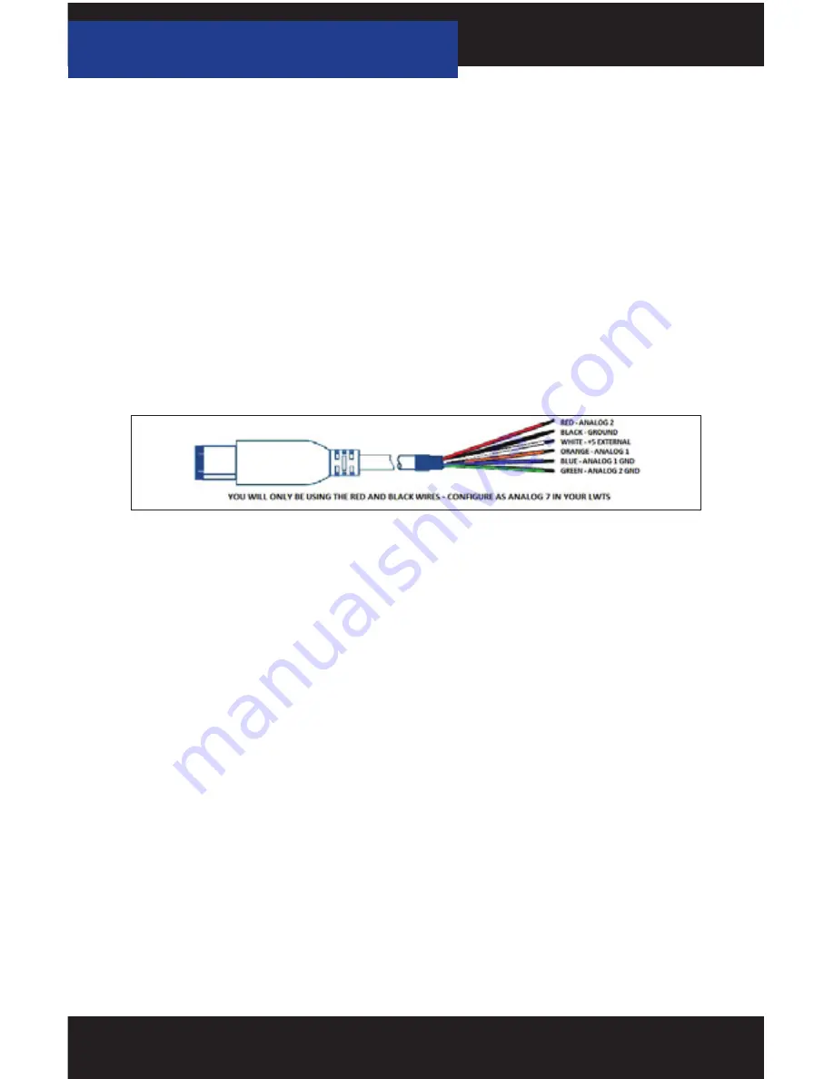
4.2 CONNECTING EXTERNAL ANALOG INPUTS
Using the wiring specifications that came with your analog sensor, connect to the
proper pins using the diagram below.
NOTE: Do not connect any device to the analog input that exceeds 5 volts to the analog port or
permanent damage to the adapter can occur.
Example of an EGT being Configured to an EGT Kit to work with your LWTS+
1. Connect 6 PIN firewire analog cable into the built-in firewire port on the OBDII cable.
2. Power on your LWTS+, on the bottom left of your home screen you will see “Gauges/
Datalog”, select it.
3. You will be prompted to turn the key to the ON position; the LWTS+ will automatically detect
your key being turned on.
4. Select the appropriate Preloaded Datalog File displayed on the screen that matches your
type of vehicle, (in this example we will use Ford Diesel 6.0L and 7.3L) Press Continue.
5. When the main gauge display comes up, Double tap on the gauge you would like to edit.
a. Single Tap: Views the Menu
b. Double Tap: Edits Gauges
6. Once you’ve double tapped the gauge, you will be brought to a screen where you can select
the proper Item to monitor, proper equation for analogs and add a Min and Max Range.
a. Item: Press and hold on the screen to scroll, all the way at the bottom where the Analogs
are located, tap “Analog In 7 Red-Wire”
b. Equation: Tap “SCT EGT F”
c. You may now modify Min and Max Value’s
7. 7. Select “Approve” to confirm the changes and view the EGT signal real-time.


