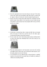
6) Press “start” to run, machine will be automatic heating;
7) After finished heated, top heater will automatic rising up to original
position and stop there;
8) cooling fan start cooling;
9) Welding is finished.
(III) Mounting process
1. Work flow:
Power on
→
Place PCB on PCB supporter
→
Place BGA
→
Adjust position
→
Fixed the splint
→
Front forward Joystick
→
Sucking BGA
→
Go Back
Joystick
→
Optical Alignment adjust image
2. Detail description
1) Fixed X axis screw, locked PCB splint.
2) Put the balled BGA chips on the PCB pad.
3) Operate joystick to front forward, make the sucking point touched BGA,
press “Vacuum” to sucking BGA;
4) Go back the joystick, let the sucker point with BGA to rising up proper
position;
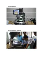
5) Drag out optical alignment to proper position (BGA center);
6) Adjust image, operating joystick from left to right as zoom in and zoom
out, micro control X, Y axis and R angle to got clearer image.
7) Push back optical alignment to original position, and there is magnetic
positioning.
8) Front joystick, top heater fall down to put BGA on correspond welding
pad, then start heating;
9) After finished heated, top heater will automatic rising up to original
position; BGA has welded on PCB;
10) So far, the mounting process is finished.
7. The use of external thermocouple wires
(I) Function
1. More accurate to measure the actual temperature of the part to be
heated during the welding process.
2. It is easy to move, so that it can be convenient to measure the
temperature of the different parts of the welded components during the


