background image

S

S

E

E

R

R

V

V

I

I

C

C

E

E


M

M

A

A

N

N

U

U

A

A

L

L


42 of 

79


___________________________________________________________________________

_______ 

ESIRIS -

- Version 1.0  Date: 22.09.00 


Camera / Active Eye-Tracking:  

The measurement of the concentric of the video camera the user has to use this 
menu point. The video image which displays the ablation area has to be checked 
with the 

Check optical alignment

 procedure. 


Check optical alignment: 

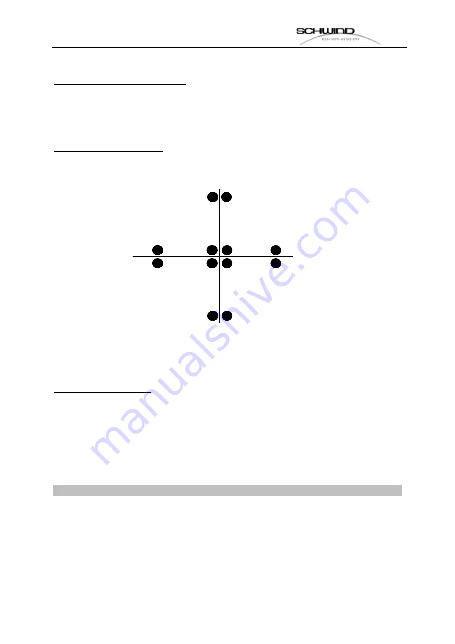
By pressing the button the laser will shot following image 


Now the user has to check if the cross-hair is in the center and has the same outlook 
like in the image above. 


Stop show histogram: 

With this function the intensity and contrast has to be checked. On the right side the 
user can see a standard histogram which is guilty for the adjustment. The red 
second histogram has to be overlapped with the standard histogram. By moving the 
intensity and contrast scrollbar it is very easy to bring both histograms together. 

If the user had done this, the alignment of the camera is OK. 

If a human eye is positioned in the ablation zone the service can check once again 
the functionality of the eye-tracking.  

Attention: The quality value should be higher than 120. 

The position POS shows the coordinates of the center of the pupil. (compare it with 
the red cross-hair.  


Summary of Contents for ESIRIS

Page 1: ...EXCIMERLASER ESIRIS SERVICE MANUAL Schwind GmbH Mainparkstrasse 6 10 D 63801 Kleinostheim...

Page 2: ...S SE ER RV VI IC CE E M MA AN NU UA AL L 2 of 79 ___________________________________________________________________________ _______ ESIRIS Version 1 0 Date 22 09 00...

Page 3: ...OPTICAL BEAM DELIVERY SYSTEM 15 3 INSTALLATION REQUIREMENTS AND PREPARATIONS 17 WORKING ROOM 17 DIMENSIONS ESIRIS 18 INPUT REQUIREMENTS 19 INSTALLATION AND ROOM PREPARATIONS FOR THE INSTALLATION 20 M...

Page 4: ...NCE DETECTOR 61 DISMANTLING THE PATIENT BED 61 DISMANTLING LASER 62 7 INSTALLATION OF THE ESIRIS LASER 63 ASSEMBLING THE LASER 63 ASSEMBLING OF THE PATIENT BED 63 ELECTRICAL CONNECTION OF PATIENT BED...

Page 5: ...ers as positioning and fixation device The output of the fixation laser is below 10 W Therefore it belongs to class 1 which allows an undefined exposition time of the eye The positioning lasers are us...

Page 6: ...Never put your skin into the laser beam Wear protection glasses Make sure that no reflection devices are placed in the area of the laserbeam Follow the instructions of the trade association VBG 93 Pe...

Page 7: ...ter of 1 0 mm Output and energy density of beam decreases accordingly with increasing distance from treatment area Protection Glasses All persons inside the room except the patient have to wear protec...

Page 8: ...ns An unintentional output of working gas is very unlikely Fluoride can be recognised through its pungent smell long before the concentration will come to maximum allowed values for working places In...

Page 9: ...laser devices for medicine purposes and to put them into circulation Conformity with the construction authorisation of the device according to the MPBetreibV is ensured under the precondition that del...

Page 10: ...pulsed Pulse energy beam output 15 mJ max Pulse frequency 200 Hz max Pulse duration 8 ns Pulse to pulse stability 5 Power density 1 5 x 10⁵ W m2 Energy density 800 mJ cm2 Beam diameter output 7 x 4 mm...

Page 11: ...B or more Processor Pentium III 500 MHz or higher Memory 64 MB Monitor 12 1 VGA flat monitor Interlock 1 opener external Monitor output VGA socket Cooling Air Cooling Circulation internal fan Electric...

Page 12: ...ltraviolet beam If the gas is arranged in an optical resonator of two parallel mirrors the laser effect is achieved and light impulses with very high maximum outputs are beamed The laser gas consumes...

Page 13: ...ctly check criterions are guaranteed Otherwise damages to the system could be coursed This is to fix into a Service and Maintenance Agreement The gas bottle will be changed by a SCHWIND service engine...

Page 14: ...are used as positioning laser Therefore they are directed punctually at the eye in an angle from left and right so that the points do cross at exact distance of focus A diode laser beams through the...

Page 15: ...ntional release of pulses The treatment procedure can be interrupted any time by releasing the footswitch The program remains active so the treatment can be continued afterwards by pushing the footswi...

Page 16: ...re in this case The pressure bottle with nitrogen has to be changed immediately To avoid a slow loss of nitrogen through little leaks at the valve of the bottle it should be closed while the ESIRIS is...

Page 17: ...ser is in use A switch which interrupts the laser if the door is opened can be connected through the interlock input at the device But this is only recommended when it is guaranteed that the door is n...

Page 18: ...VI IC CE E M MA AN NU UA AL L 18 of 79 ___________________________________________________________________________ _______ ESIRIS Version 1 0 Date 22 09 00 Dimensions ESIRIS Picture 2 Dimenstions ESI...

Page 19: ..._ _______ ESIRIS Version 1 0 Date 22 09 00 Picture 3 Dimensions ESIRIS front Picture 4 Dimensions ESIRIS side Input Requirements SCHWIND ESIRIS needs as electrical input Electric connections 1 2 kVA P...

Page 20: ...dimentions ideally 12 m Requirements for the floor can be seen in above ground plan drawing Floor requirements Laser system and beam delivery system 250 kg Point weight through supporting feet at the...

Page 21: ...SIRIS adjusted at 8 l min flow Darkening shutter Air conditioning in countries with temperatures of more than 25o C or differences of more than 10 An air drier is absolutely necessary in countries wit...

Page 22: ...delivered in two parts packed separately the laser with the optical system the patient bed and containment and necessary spare parts control monitor and keyboard Packing consists of two screwed wooden...

Page 23: ...owing chapter gives you a description of the service software functions in the ESIRIS software By using the service password the service get following main menu with the pull down menu Extra and Servi...

Page 24: ...0 last old entries in a separate file with the name logfile date bak This is a normal text file which can be read with any text editor program Menu Parameter In the parameter menu the service can chan...

Page 25: ...igmatism Laser On the bottom of the formular the service can store the laser energy which is responsible for all treatment methodes The laser frequency is only displayed but not changeable The number...

Page 26: ...S SE ER RV VI IC CE E M MA AN NU UA AL L 26 of 79 ___________________________________________________________________________ _______ ESIRIS Version 1 0 Date 22 09 00 Picture 9 Distributor adress...

Page 27: ...te 22 09 00 By using the service menu in the menu task bar the service can use several service functions which are necessary for the adjustment of the laser or to test and check the systems in case of...

Page 28: ...VI IC CE E M MA AN NU UA AL L 28 of 79 ___________________________________________________________________________ _______ ESIRIS Version 1 0 Date 22 09 00 On the next pages all menus will be explaine...

Page 29: ...p the service can see the laser type the bios version of the laser and the COM interface The TX RX icons are blinking in case of a right connection between the PC and the laser Pressure On the top the...

Page 30: ...ysiks for detailed information Errorcode 1 Check error occurred statical error Errorcode 2 Time out error operation error laser device is to be switched off Errorcode 3 Laser head chamber open or temp...

Page 31: ...ternal energy powermeter error occurred Errorcode 12 HV too high error occurred Errorcode 13 CPU error occured Errorcode 14 HV temperture error occurred Status 2 and Status 3 The Status 2 and Status 3...

Page 32: ...9 00 Rep Repetition mode ext trigger external trigger is activated Quant Quantity burst mode is activated Watchmode Watchmode is activated RegEn Energy Const mode is enabled Eregakt Current energy set...

Page 33: ...r has to press the Laser On button After this it is possible to activate different laser modes Modus Intern Trigger Start the internal trigger Extern Trigger Laser is waiting for external trigger Quan...

Page 34: ...the button the user can switch between both modes Above the current energy or the current HV will be displayed In the nominal HV or energy input mask the user can set different values Attention Please...

Page 35: ...technical security check Picture 12 Scanner menu In this menu the user has the possibility to set the X and Y offset of the scanner The first X and Y offset is responsible for the zero position of th...

Page 36: ...photopaper After the procedure the user has to check with a lens meter the distance from one point to the other point and to measure if he has a rectangle of 10 X 10 mm In case it is not ok he has to...

Page 37: ...S SE ER RV VI IC CE E M MA AN NU UA AL L 37 of 79 ___________________________________________________________________________ _______ ESIRIS Version 1 0 Date 22 09 00 Picture 13 Digital input...

Page 38: ...___________________________________________________________________________ _______ ESIRIS Version 1 0 Date 22 09 00 Picture 14 Digital output The Output window shows the switchable functions By clic...

Page 39: ...tainment menu allows the user to switch the gas valves and to do a gas bottle change Picture 15 Gascontainment The digital input window shows the current pressure If the pressure is OK the lamp is lig...

Page 40: ...ing this button the gas bottle change procedure will be activated Please follow the displayed instructions The current bottle pressure will be displayed in the premix bottle pressure window Menu adjus...

Page 41: ...ser pulses for watch mode Watchmode Shows the number of pulses the user had done Laser energy Shows the current laser energy Scanner X axis set a drift of the scanner for testing Y axis set a drift of...

Page 42: ...ter and has the same outlook like in the image above Stop show histogram With this function the intensity and contrast has to be checked On the right side the user can see a standard histogram which i...

Page 43: ...ter this test the user has to check with a lensmeter if he has such profile If not then the adjustment of the optics has to be checked again Pinhole adjustment By selecting the pinhole adjustment func...

Page 44: ..._______________________________________________________ _______ ESIRIS Version 1 0 Date 22 09 00 Menu Technical Secutity Check TSC If the user is selecting this menu he will asked if he had done the T...

Page 45: ...ection Disregard would invalid warranty Device has been packed properly in perfect condition at factory Transportation damages are in the responsibility of transporting agent In case such damages are...

Page 46: ...mitted installation starting or use of the device invalidates warranty The service technician inspects the room for necessary installations space voltage connection security regulations and ventilatio...

Page 47: ...delivery note through the customer Warranty time for SCHWIND ESIRIS lasts 12 months Warranty includes all defects of the device caused through defective parts or manufacturing Further malfunctions th...

Page 48: ...move the patient bed together with the gas containment from the complete laser system Before disconnecting the gas tube from valve plugs of the Optex laser you have to be sure that no more premix gas...

Page 49: ...S SE ER RV VI IC CE E M MA AN NU UA AL L 49 of 79 ___________________________________________________________________________ _______ ESIRIS Version 1 0 Date 22 09 00...

Page 50: ...press the button Abort to interrupt the whole premix bottle exchange procedure 5 Loosen the connection pig tail to premix bottle with open end wrench 6 Mount screw cab onto Premix gas bottle and pig...

Page 51: ...gas containment 10 Shut down the PC switch off the system by turning the main key and unplug the power line connection Hint in fact of using an uninterruptable power supply UPS switch it off and also...

Page 52: ...Use plastic yellow screw cabs to prevent the gas tube 16 Connect again the optical trigger cable and the optical RS 232 cable to the Optex laser 6 2 Unplug electrical connections of patient bed CAN B...

Page 53: ...S SE ER RV VI IC CE E M MA AN NU UA AL L 53 of 79 ___________________________________________________________________________ _______ ESIRIS Version 1 0 Date 22 09 00...

Page 54: ...9 00 2 Then bring back these cables to stick them to the patient bed 3 Afterwards loosen the screw 13 mm key of the earthing socket 6 3 Dismantling of optical parts Dismantling of microscope 1 Loosen...

Page 55: ..._______________________________________________________________ _______ ESIRIS Version 1 0 Date 22 09 00 Dismantling CCD camera tower 1 Remove the 25 pole plug of the CCD camera 2 Loosen the BNC cable...

Page 56: ..._________________________ _______ ESIRIS Version 1 0 Date 22 09 00 4 Loosen the 4 screws of the CCD camera tower 5 After removal of the CCD camera tower tighten the screws again with the hands to prev...

Page 57: ...______________________________________________________________________ _______ ESIRIS Version 1 0 Date 22 09 00 8 Fixate the cables at the optical arm with tape Dismantling Scanning mirror 1 Open the...

Page 58: ...IS Version 1 0 Date 22 09 00 3 Loosen the 4 srews allenwrench 4mm of the scanner and hold the scanner with your hands attention do not touch the mirrors mounted on the galvos 4 After removal of scanne...

Page 59: ..._____________________________________________________ _______ ESIRIS Version 1 0 Date 22 09 00 Nitrogen gas cylinder 1 Unplug nitrogen tube at nitrogen management Dismantle Monitor and Keyboard 1 Loos...

Page 60: ..._______ _______ ESIRIS Version 1 0 Date 22 09 00 2 Unplug the cables for the keyboard and the trackball at the back side of the PC left keyboard right trackball 3 Unplug VGA connector and pull both ca...

Page 61: ...keyboard holder with allenwrench 8mm Disconnection of the fluence detector 1 Unplug the fluence cable at the fluence detector 2 Fixate the cable with tape at the system Dismantling the Patient Bed 1...

Page 62: ...____ _______ ESIRIS Version 1 0 Date 22 09 00 Dismantling Laser 1 The 4 feet of the laser must be screwed up step by step and not one after the other otherwise the laser could cant Danger Screw the fe...

Page 63: ...otate free 2 Unscrew all 4 wheels and put them away 3 Screw down all the 4 feet step by step not one after the other otherwise the laser could cant Danger Screw the feet down to a distance of 8 cm fro...

Page 64: ...Date 22 09 00 3 Screw down the 4 feet of the bed until the wheels rotate free unscrew them and put them away 4 Screw down all the 4 feet to a distance of 8 cm from floor to the bottom edge of the lass...

Page 65: ...S SE ER RV VI IC CE E M MA AN NU UA AL L 65 of 79 ___________________________________________________________________________ _______ ESIRIS Version 1 0 Date 22 09 00...

Page 66: ...1 First put all the cables and light fibers through the laser rack 2 Connect the following cables 24 VDC Gas 9 pin Sub D Connector CAN Gas M Patient bed T RS 232 cable of patient bed controller to CO...

Page 67: ...Version 1 0 Date 22 09 00 Assembling of Monitor and Keyboard 1 Assemble the metal arm for the table of monitor and keyboard to the laser rack 2 Build in the monitor and keyboard in the table and thre...

Page 68: ...RIS Version 1 0 Date 22 09 00 3 Connect the keyboard to the according jacks at the back side of the PC left keyboard right mouse Connect the monitor cable to the according jack at the back side of the...

Page 69: ...era Tower 1 Remove tape of the cable of the camera tower 2 Remove dust cover of radiation exit aperture 3 Remove tape of the camera aperture on the laser arm 4 Remove the four screws for the camrea to...

Page 70: ...0 Assembling the Scanner 1 Remove the tape of both apertures at laser and scanner 2 Connect scanner with four screws to the laser arm 3 Connect the cables of the scanner to the cables that come out of...

Page 71: ...as pipe 2 Remove yellow protection cap from the valve block of the Optex laser 3 Connect the gas pipe from the gas containment with the the valve block of the Optex laser and tighten it using the scre...

Page 72: ...___________________ _______ ESIRIS Version 1 0 Date 22 09 00 10 Connect the ESIRIS to the UPS and switch it on with the main key switch Log in with service authority 11 Choose menu SERVICE gas contain...

Page 73: ...he center of the tube opening behind the 2nd mirror 3 Insert the 1st lense and check if the beam is still in the center 4 Insert all the other parts into the optical tube integrator pinhole 2nd mirror...

Page 74: ...the bounding of the corneal surface or to rise it If furthermore an astigmatism should be corrected the bounding of the cornea has to be changed differently in two meridians Picture 17 Schematic draw...

Page 75: ...ecessary For adaptation of power density which influences an area element to an angle of incidence it is enough to take the norm bending radii of cornea R 7 8 mm A2 Correction of Myopia Geometric rela...

Page 76: ...d of single ablation zones is pre set through diameter input into the software Appendix B Beam Delivery System B1 Optical System The beam delivery system forms the beam of the excimer laser in the req...

Page 77: ...and comes then to the 2 bending mirror and is changed to 90 Through a further lens which enlarges the beam the beam comes to a scanning mirror Then the beam is enlarged through two further lenses unti...

Page 78: ...under control of the operating microscope with two red pilot laser beams one from the left and one from the right which are directed to the cornea in an angle They meet at the cornea at the working d...

Page 79: ...or room dimsions ideally 12m 20 Picture 6 Truck Dimension 22 Picture 7 Main menu 23 Picture 8 Parameter menu 24 Picture 9 Distributors adress 25 Picture 10 Service Menue 26 Picture 11 Laser menu 27 Pi...

Reviews: