INSTALLATION
MOUNTING
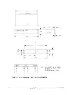
The SEL-267D relay is designed for mounting by its front vertical flange in a 19-inch vertical
relay rack. It may also be mounted semi-flush in a switchboard panel. Four #10 screws
should be used for mounting. Front and rear panel drawings are included in the appendices.
FRAME GROUND CONNECTION
Terminal 46 on the rear panel must be connected to frame ground for safety and performance.
These terminals connect directly to the chassis ground of the instrument.
POWER CONNECTIONS
Terminals 44 and 45 on the rear panel must be connected to a source of control voltage.
Control power passes through these terminals to the fuse or fuses and toggle switch, if
installed. It continues through a surge filter and connects to the switching power supply. The
control power circuitry is isolated from the frame ground.
SECONDARY CIRCUITS
The SEL-267D relay presents a very low burden to the secondary current and potential
circuits. Each current circuit is independent of the others; there is no interconnection of
current circuits inside the instrument. When current polarization is not desired or required,
Terminals 35 and 36 may be left open-circuited.
The SEL-267D relay requires three-wire potentials. It is not possible to directly apply the
SEL-267D relay to circuits where wye-connected potential transformers are used. Please
consider the SEL-267 or SEL-221G for such applications.
Date Code 920326
Installation
SEL-267D Instruction Manual
5-1
Summary of Contents for SEL-167D
Page 3: ......
Page 6: ......
Page 8: ......
Page 9: ......
Page 10: ......
Page 11: ......
Page 51: ...LOGIC DIAGRAMS Date Code 920326 Specifications SEL 267D 167D Instruction Manual 2 31 ...
Page 52: ...Date Code 920326 Specifications 2 32 SEL 267D 167D Instruction Manual ...
Page 53: ...Date Code 920326 Specifications SEL 267D 167D Instruction Manual 2 33 ...
Page 54: ...Date Code 920326 Specifications SEL 267D 167D Instruction Manual 2 34 ...
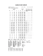
Page 88: ...SAMPLE EVENT REPORT ...
Page 114: ......
Page 115: ......

