background image

14

VarioProtect XXL-W TC AIR TH3 | Version 1.06 | EN

Utilization

13 Utilization

13.1  Adjustment of the air flow

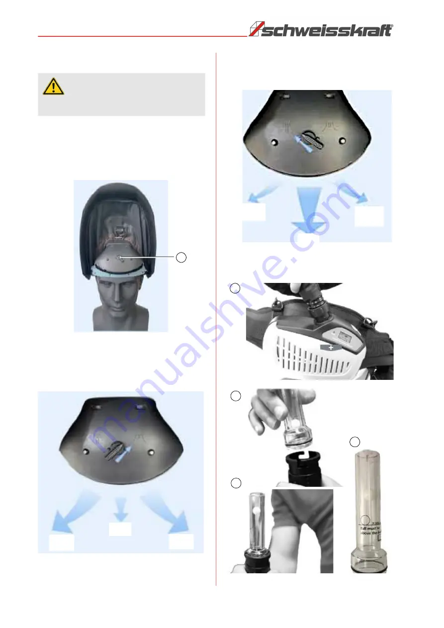
The air flow can be set in two ways using the switch on 

the front of the inner hood (item 1, figure 15).


Fig. 15: Switch to adjust the flow

When the switch is in the right position, distribution takes 

place in three zones (Fig. 16). The two outer zones each 

receive 40% and the middle zone 20% of the air flow. 

Fig. 16: Air distribution 40 %,20 % and 40%

With the switch in the left position, distribution is also car

-

ried out in three zones (Fig.17). The two outer zones each 

receive 10% and the middle zone 80% of the air flow. 

Fig. 17: Air distribution 10%,80% and 10%

13.2  Air flow test

Fig. 18: Air flow test 

ATTENTION!

Never use the welding helmet with the fan switched 

off.

1

40 %

20%

40 %

10%

10%

80%

1

2

3

4

Summary of Contents for VarioProtect XXL-W TC AIR TH3

Page 1: ...VarioProtect XXL W TC AIR TH3 Operating Instructions VarioProtect XXL W TC AIR TH3 VARIO PROTECT Automatic welding helmet with air filter system ...

Page 2: ...3 Setting of the operating mode 9 8 4 Setting of the the protection level 9 8 5 Memory 9 8 6 Adjustment options of the headbands 10 8 7 Setting the air flow level 10 9 Unpacking Assembling 10 10 Warning notices 11 11 Procedure for recognizing a failure of the darkening filter 11 12 Before putting into commissioning 11 12 1 Inserting the battery 11 12 2 Acoustic warning signal of the charge level 1...

Page 3: ...provide you with expert advice and information Germany Stürmer Maschinen GmbH Dr Robert Pfleger Str 26 D 96103 Hallstadt Repair Service Fax 0951 96555 111 Email service stuermer maschinen de Spare parts order Fax 0951 96555 119 Email ersatzteile stuermer maschinen de We are always interested in information and experiences that result from the application and that can be valuable for improving our ...

Page 4: ...stated in these operating instructions Use only original spare parts Unauthorized spare parts can involve risks and will invalidate the guarantee If the viewing window does not darken immediately af ter the welding arc is ignited welding must be stopped immediately Contact your supervisor or your dealer im mediately Do not immerse the viewing window in water Do not use solvents on the viewing wind...

Page 5: ...system protects against parti cle contamination in accordance with the requirements of EN 12941 equipment class TH3P To ensure nominal protection no leakage may occur while wearing the wel ding helmet Intended use also includes compliance with all the infor mation in these instructions 3 1 Reasonably foreseeable Misapplication Any use beyond the intended use or any other use is considered misuse P...

Page 6: ... Protection level 4 Dark protection levels colour selection 5 9 and 9 13 Number of sensors 4 ON OFF Fully automatic Solar cells yes Class 1 1 1 1 Functions WELD welding GRIND grinding Changeover response time from light to dark 0 08 ms Lightening time DELAY from dark to light 100 ms to 900 ms continuous Application temperature 5 C to 55 C Replaceable battery yes rechargeable 4400 mAh Battery charg...

Page 7: ...stment of the protection levels SHADE 12 Operating mode switch WELD GRIND 13 Hose connection Fig 3 Display Battery indicator If the battery capacity is low the battery must be changed Otherwise the lighten and darken times will slow down 3 4 6 7 8 2 1 5 9 1 1 1 1 Button Battery status display Operating mode display WELDING Operating mode display GRIND Display color selection protection levels 5 9 ...

Page 8: ...e disposal company 7 3 Storage The welding helmet must be thoroughly cleaned and stored in a dry clean environment at temperatures be tween 10 C and 55 C and a relative humidity of be low 90 If the welding helmet is not used for a longer period of time the battery must be fully charged removed from the filter system and stored separately 8 Product properties and setting op tions The shape of the h...

Page 9: ...rkening function is switched off 8 4 Setting of the the protection level The protection levels from 5 to 9 or from 9 to 13 are se lected with the protection level button SHADE on the in side of the helmet Fig 6 To do this press the button repeatedly until the desired value appears in the display The welding filters completely protect the welder s eyes and face from UV and IR radiation during weldi...

Page 10: ...ide of the helmet move the helmet to the appropriate position and tighten the knobs again The adjustment options of the headband result in maxi mum wearing comfort 8 7 Setting the air flow level The respirator system offers three settings for the air flow to the helmet The appropriate level can be set as re quired and should be tested by the user before starting the welding work To switch off hold...

Page 11: ...r Always wear the complete respirator system and do not remove the head plate or never switch the air filter unit off outside the contamination area Otherwise there is a risk that a high concentration of CO2 will develop and the oxygen content in the upper part of the head will drop and thus little or no protection will be given If you are unclear about the pollutant concentration or about the per...

Page 12: ...rged and then discharged twice and then charged again in order to maintain its full capacity Step 1 Connect the battery to the charger The contact is on the top of the battery Step 2 Connect the charger to the mains The charging status is indicated by the red LED on the charger As soon as the battery is fully charged the char ger switches to trickle charging The LED display changes to green Step 3...

Page 13: ...ilter system over and attach the Velcro to the belt Step 6 Put the fastening strap back through the 2 belt loops Step 7 Fasten the belt buckle again Step 8 Attach the strap to the 4 plastic rings on the strap Step 9 Check that the belt is securely fastened 12 5 Connecting the air line Fig 14 Connecting the air line Step 1 Connect the air tube to the respirator system and turn it clockwise to lock ...

Page 14: ...bution takes place in three zones Fig 16 The two outer zones each receive 40 and the middle zone 20 of the air flow Fig 16 Air distribution 40 20 and 40 With the switch in the left position distribution is also car ried out in three zones Fig 17 The two outer zones each receive 10 and the middle zone 80 of the air flow Fig 17 Air distribution 10 80 and 10 13 2 Air flow test Fig 18 Air flow test AT...

Page 15: ...pipe with your hand to block the airflow and wait approx 15 seconds The alarm must be triggered during this period If the alarm does not work the respirator system must be repaired or replaced 13 4 Adjustment of the helmet Fig 20 Adjustment of the headband Step 1 Pull the ring up to open the fabric seal and put the helmet on Step 2 Adjust the headband so that the helmet fits exact and tight To do ...

Page 16: ...rs Outer lens soiled or damaged Replace or clean the outer lens Sensitivity is set too low or the delay time is set too short Set to required value Unsuitable protection level set Set a suitable protection level Automatic cassette darkens without arcing Sensitivity is set too high Set to required value The automatic cassette remains darkened after the welding process has been completed The delay t...

Page 17: ...hes Acoustic alarm signal sounds Low battery capacity Charge the battery Filter symbol and warning flashes Acoustic alarm signal sounds 1 Filter clogged 2 Clogged line 1 Clear the filter or line and clean it 2 Replace filter if necessary Filter symbol flashes Acoustic alarm signal sounds High battery temperature Interrupt work and take a break to cool off the battery No air flow no alarm 1 No powe...

Page 18: ... the protection class against impact energy flying parts F stands for low impact energy 45 m s and B stands for medium impact energy 120 m s If the protective equipment also meets the requirements for extreme tem peratures 5 C to 55 C it is also marked with the letter T welding procedure metal arc welding MIG welding for heavy metal MIG welding for light alloy Tungsten inert gas welding Semi autom...

Page 19: ...w the inner lens and lift up the inner lens 2 Insert the new inner lens Replacement of the filter 1 Remove the filter cassette from the helmet shell Fig 25 Bend up the top of the filter housing to remove the filter cassette from the frame 2 Insert the new filter cassette into the frame Fig 26 Make sure the filter cassette is properly seated in the frame and put the filter casette back into the hel...

Page 20: ...e filter should be replaced together with the prefilter 18 5 Replacing the air filter Fig 27 Filter replacement The service life of the filter and prefilter is 12 months With intensive use the condition of the filter should be checked regularly at shorter intervals If necessary re place the filter parts more frequently than every 12 months Step 1 Remove the filter cover by pressing the latch on th...

Page 21: ...ry can either be inserted in the filter unit or charged separately Fig 30 Battery charger The battery charger charges the battery automatically As soon as the battery is fully charged the charger switches to trickle charging viz the charge level is kept at 100 Charging time 3 to 4 hours Charge the battery every 15 days ATTENTION The battery must be charged to 100 before start ing operation 1 2 ATT...

Page 22: ...es if pres ent If necessary dismantle the automatic welding helmet into manageable and usable assemblies and compo nents Take the components to the designated disposal routes 19 2 Disposal via municipal collection points Disposal of used electrical and electronic equipment Applicable in the countries of the European Union and other European countries with a separate collection sys tem for these ap...

Page 23: ...pe plate is mounted on the device Example The filter for the respirator system must be ordered The filter has the number 11 in the spare part drawing 2 By ordering spare parts send a copy of the spare parts drawing 2 with the marked part filter and marked posi tion number 11 to the dealer or spare parts department and provide the following information Device type Automatic welding helmet VarioPro ...

Page 24: ...e part drawings The following drawings are intended to help you identify the necessary spare parts in the event of service If necessary send a copy of the parts drawing with the marked components to your dealer Fig 31 Spare part drawing 1 welding helmet headbands cassette ...

Page 25: ...Spare parts VarioProtect XXL W TC AIR TH3 Version 1 06 EN 25 Spare parts drawing 2 Fig 32 Spare part drawing 2 VarioProtect XXL W TC AIR TH3 ...

Page 26: ...s testing marking DIN EN 166 2002 04 Personal eye protection Specifications DIN EN 175 1997 08 Personal protection Equipment for eye and face protection during welding and allied processes DIN EN 379 2009 07 Personal eye protection Automatic welding filters The manufacturer bears sole responsibility for issuing this declaration of conformity Responsible for documentation Kilian Stürmer Stürmer Mas...

Page 27: ...Notes VarioProtect XXL W TC AIR TH3 Version 1 06 EN 27 22 Notes ...

Page 28: ......

Reviews: