GP-M40J-CX-08A
4001/2-J, 4N11/2-J Manual
RD: April 2006
R.L. 08A
KH
ASSEMBLY..... CONTINUED
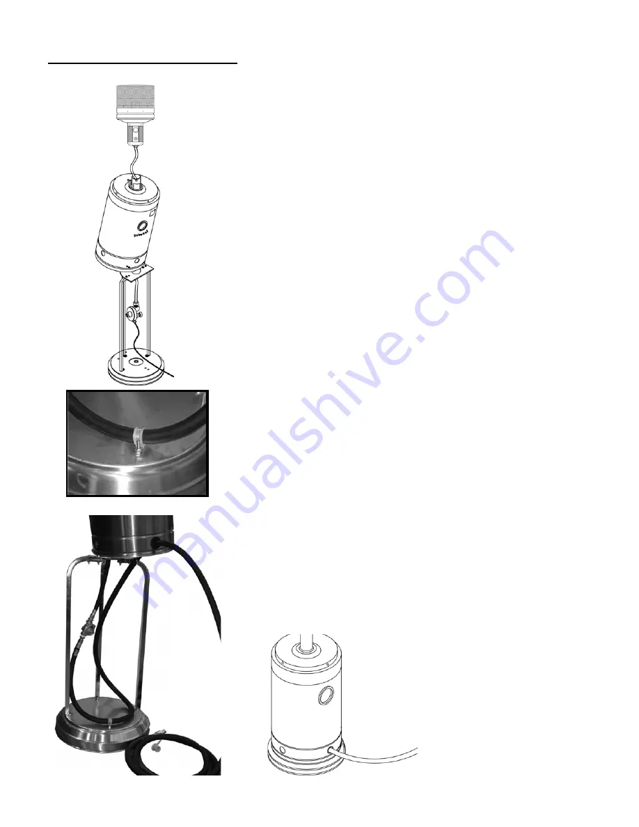
Slide cylinder cover over post and let rest in upper position.
For
LP
connection:
•
Slide gas hose up the post with LP regulator at bottom (regulator will
be inside tank cover)
•
Attach hose securely to burner
•
Allow burner to rest in post
•
Connect hose to gas cylinder.
•
Lift burner and leak test all connections
•
Fasten burner securely in place with four 1/2” machine screws
•
Attach assembled reflector (see next page)
For
NG
connection:
•
Attach 45” hose securely to burner
•
Slide hose down through inside of post
•
Attach burner to post with two 1/2” machine screws - finger tight only
(burner will need to be lifted later to leak test gas hose connection)
•
Install outlet side of 5” wc gas regulator onto hose using 1/2” pipe
thread to flared fitting adapter
•
Install 1/2” male pipe thread of 18 ft rubber gas hose into gas regulator
inlet side.
•
Remove finger tight nut from #10 bolt extending from top side of base
•
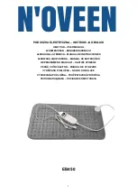
Using hose clamp provided, secure rubber gas hose to the #10 bolt
extending from top side of base
•
Leave sufficient “slack in hose above the clamp to allow for lifting
of the burner for leak testing
•
Install female quick connect provided to gas supply and connect
heater to the gas supply
•
Lift burner and leak test all gas connections
•
Secure burner with four 1/2” machine screws
•
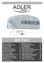
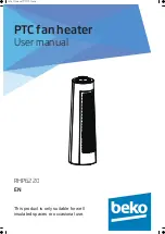
Install heavy duty grommet in one of the lower holes in the tank cover
•
Disconnect gas hose from supply and feed gas hose through the
heavy duty grommet
•
Fill counterweight container (supplied) with sand or water and place
on cylinder base
•
Slide tank cover down into place - carefully slide hose out though
grommet while tank cover descends
•
Attach assembled reflector—see next page for instruction
Page 9


