background image


Functional description 


03.00|WDP-5X |en 

57 


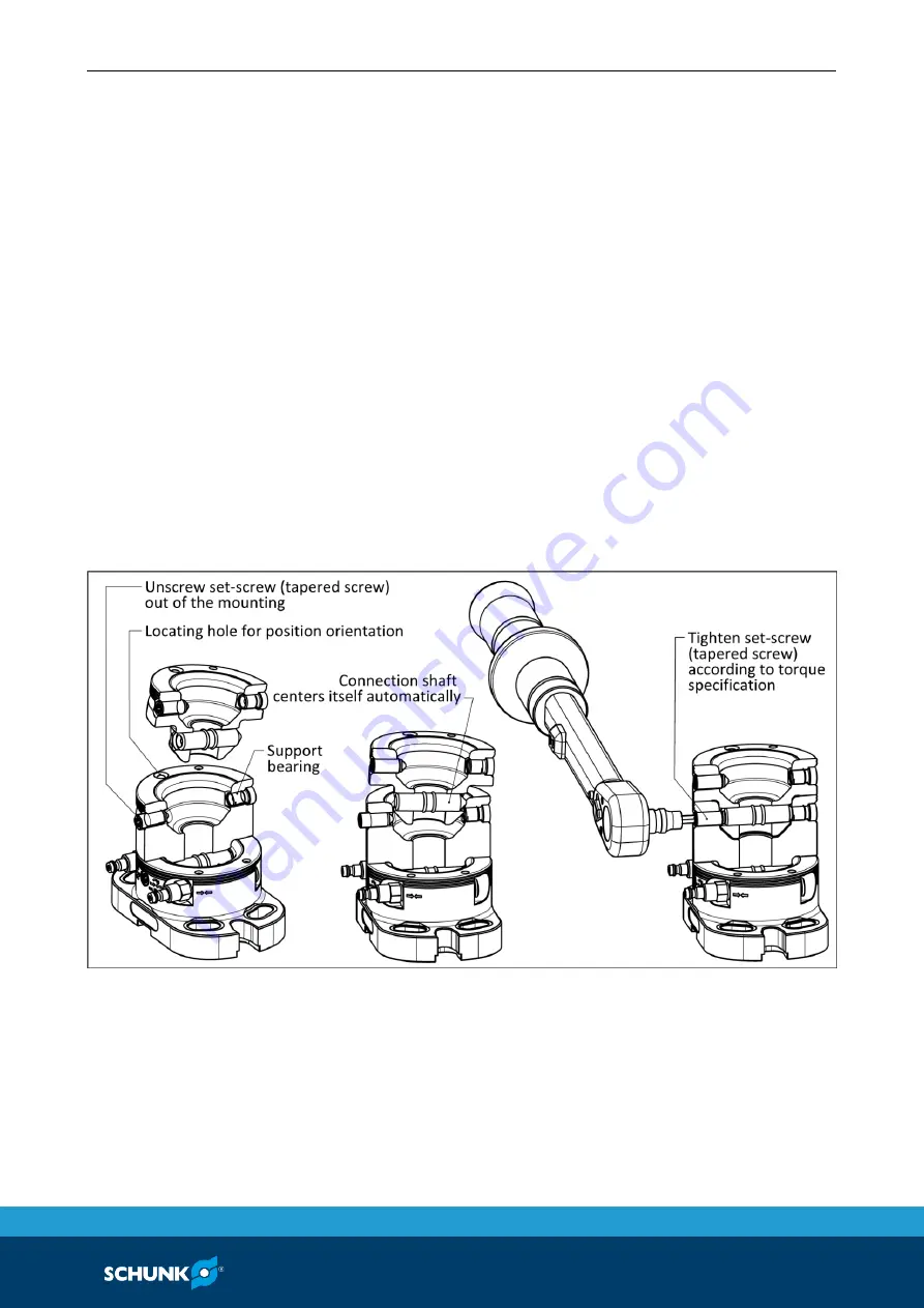
When changing an additional modular system component, the 
tapered screw at the intake interface of a base module or stacking 
module must be turned back clockwise until the tapered tip of the 
screw does not protrude into the taper mounting. 

The contact surfaces of the clamping systems must be clean and 
dry before changing. Make sure that the sealing elements for the 
compressed air routing are not damaged. The change components 
can now be changed into the unlocked intake interface. In doing 
so, ensure that they are installed in the correct direction. A 
cylindrical pin is intended as a guide.  

The clamping systems can be fixed using the T-handle hexagonal 
socket screw driver included. For clamping, the precise screw 
tightening torque must be initiated at the clamping area. The 
connection point is hereby fixed and positioned.  

A tapered screw is included in the scope of delivery as a spare 
part. 

Sequence when substituting a stacking module into the change 
interface


Summary of Contents for VERO-S

Page 1: ...Translation of Original Operating Manual VERO S modular system for direct workpiece clamping WDP 5X Assembly and Operating Manual Superior Clamping and Gripping...

Page 2: ...he purpose of technical improvement Document number 0489075 Version 03 00 21 10 2019 en H D SCHUNK GmbH Co All rights reserved Dear Customer thank you for trusting our products and our family owned co...

Page 3: ...w strength 13 2 9 Transport 13 2 10 Malfunctions 14 2 11 Disposal 14 2 12 Fundamental dangers 14 2 12 1 Protection during handling and assembly 15 2 12 2 Protection during commissioning and operation...

Page 4: ...1 5 7 Clamping pin extensions SP VLK 50 52 5 8 Pneumatic circuit diagram 52 5 9 Compressed air supply 54 6 Functional description 56 6 1 Function of the connecting unit in the change components 56 6 2...

Page 5: ...ns in this manual are provided for basic understanding and may differ from the actual product design In addition to these instructions the documents listed under 1 1 2 Page 6 are applicable Presentati...

Page 6: ...es of VERO S WDP 5X workpiece direct clamping modules or 50 000 cycles for VERO S clamping systems WDP 5X DSM 99 70 20 000 cycles for VERO S clamping systems WDP 5X ASM 99 70 36 and WDP 5X ASM 99 70 3...

Page 7: ...K 50 Clamping pin extension SPC VLK 50 Assembly and Operating Manual ID 0489071 Accessory kit WDP 5X BM 99 60 1 grub screw WDP 5X 99 50 spare part 4 fixing screws M12 x 40 2 fixing screws M16 x 55 2 w...

Page 8: ...25 SPC VLK 50 1 sleeve HUE 24 25 Accessories see catalog or data sheets when ordering separately Blank of a clamping pin type BRR Thread bore hole grid plates Clamping pallets type PAL S PAL A Clampin...

Page 9: ...this manual Not intended use The VERO S WDP 5X clamping system is not being used as intended if for example It is used as a pressing tool a toolholder a load handling device or as lifting equipment It...

Page 10: ...sure that the product is used only in the context of its defined application parameters 3 Page 20 Make sure that the product is a sufficient size for the application Make sure that the contact surface...

Page 11: ...Due to their technical training knowledge and experience trained electricians are able to work on electrical systems recognize and avoid possible dangers and know the relevant standards and regulation...

Page 12: ...ardous substances Wear close fitting protective clothing and also wear long hair in a hairnet when dealing with moving components Notes on safe operation Incorrect handling of the personnel Incorrect...

Page 13: ...imited by the strength of the screwed connections with which the clamping pin is connected to the pallet or device On this basis fastening screws of the property class 12 9 are to be used only Only or...

Page 14: ...ng of disposal may impair the product s safety and cause serious injuries as well as considerable material and environmental harm Follow local regulations on dispatching product components for recycli...

Page 15: ...e assembly and transport equipment and take precautions to prevent jamming and crushing Incorrect lifting of loads Falling loads may cause serious injuries and even death Stand clear of suspended load...

Page 16: ...the current operating condition of the drive Perform maintenance work modifications and attachments outside the danger zone defined by the movement range To avoid accidents and or material damage huma...

Page 17: ...gence During operation incorrect or negligent loosening of the clamping pin must be prevented using suitable countermeasures disconnecting the power supply after locking use of check valves or safety...

Page 18: ...in the exhaust and air purge connections of the clamping station The danger zone must be surrounded by a protective enclosure during operation Wear personal protective equipment safety goggles CAUTION...

Page 19: ...dent prevention regulations when operating the quick change pallet system especially when working with machine tools and other technical equipment CAUTION Risk of burns due to workpieces with high tem...

Page 20: ...m 60 mm 60 mm 30 mm Change interface holding force 50 kN Change interface pull in force min 10 kN max 25 kN Change interface actuation moment min 20 Nm max 50 Nm Weight 4 2 kg 3 1 kg 2 9 kg 1 7 kg Des...

Page 21: ...uality according to ISO 8573 1 7 4 4 Tightness level IP IP 67 Holding force when fastening the clamping pin with cylindrical screw DIN EN ISO 4762 12 9 Manual direct clamping module WDP 5X DSM 99 70 M...

Page 22: ...Actuating pressure 6 bar Repeat accuracy 0 15 mm radially floating compensation Noise emission 70 dB A Pressure medium Compressed air compressed air quality according to ISO 8573 1 7 4 4 Tightness lev...

Page 23: ...ality 10 9 Screw size M10 M12 M16 Maximum admissible torques MA Nm 52 92 224 Screw tightening torques for the attachments screw of the change interface for connecting two joined workpiece direct clamp...

Page 24: ...elivery is complete and that there is no transport damage Assembly dismantling and modification work on the workpiece direct clamping module may only be carried out by specialist personnel Disconnect...

Page 25: ...cy between several quick change pallet systems VERO S WDP 5X the clamping pins or the clamping pin extensions with positioning accuracy in one direction SPB 40 SPB VLK 50 must be used for clamping sys...

Page 26: ...pressure ventilation would have to take place via an open air connection on the WDP 5X BM 99 60 or WDP 5X BMG 99 60 base module The connection may not be closed by a locking screw for this as otherwis...

Page 27: ...ations to the machine table slots The clamping system can be positioned on machine tables with hole pattern bore holes or machine tables with T slots for screw connection via the central bore hole in...

Page 28: ...SM 99 70 Via the integrated air forwarding in the exchange interfaces a direct clamping module WDP 5X DSM 99 70 M or a compensation module WDP 5X ASM 99 70 can be controlled If a pneumatic clamping sy...

Page 29: ...Assembly 03 00 WDP 5X en 29...

Page 30: ...Assembly 30 03 00 WDP 5X en...

Page 31: ...Assembly 03 00 WDP 5X en 31 Mounting the WDP 5X BM 99 60 on grid plates Mounting the WDP 5X BM 99 60 on a T groove table...

Page 32: ...the machining forces The integrated change interface of the clamping system has a central connection screw for clamping an adaptable stacking module WDP 5X SM or a workpiece direct clamping module WDP...

Page 33: ...Assembly 03 00 WDP 5X en 33 Mounting and connection WDP 5X BMG 99 60...

Page 34: ...ompensation module WDP 5X ASM 99 70 36 can be controlled If a pneumatic clamping system is to be supplied with compressed air on the clamping pillars the closing nipples included in the scope of deliv...

Page 35: ...hole plates with centering bores 24 H6 H7 mm and tapped hole M16 in bore hole grid spacing 50 mm x 50 mm The technical equipment features and the functions are identical to the basic module WDP 5X BM...

Page 36: ...Assembly 36 03 00 WDP 5X en...

Page 37: ...have two change interfaces with which the units can be joined together The fastening to the already mounted clamping system is done by means of an integrated shaft connection in the clamping unit The...

Page 38: ...llation position a cylindrical pin grips into the interface to be inserted The stacking module has integrated routing air for the functions unlocking turbo function and workpiece contact monitoring Th...

Page 39: ...with compressed air via the integrated air routing of the change components assembled on top of each other The quick change pallet module is a system secured by a spring The unlocking of the VERO S c...

Page 40: ...g function with which whether the work surface of the workpiece or the clamping pallet is flat can be monitored via a differential pressure switch see chapter Function of the workpiece monitoring func...

Page 41: ...side of the housing The clamping system can be operated by means of a hexagonal screwdriver angled pin wrench The clamping force is initiated according to the precise torque specification using a tor...

Page 42: ...for flexible workpiece support For positioning in the plane of fixation gauge tolerances for the reference clamping areas can be compensated Angle tolerances to the workpiece can be compensated at an...

Page 43: ...oosened via the compressed air supply of the base module or basic module The change interface is suitable for the WDP 5X SM stacking modules An upcoming compressed air supply from the stacking modules...

Page 44: ...cise torque specification using a torque wrench No air supply is required for operation of the clamping system This compensation module satisfies the clamping and holding function for flexible workpie...

Page 45: ...s are suitable for use on clamping structures with precisely aligned height supports on the workpiece or the clamping pallet If variable height distances on the workpiece or the clamping pallet are to...

Page 46: ...mbered in the preferred order These clamping pins are preferably to be used with precisely height coordinated workpiece gradings These do not allow any height tolerances to be compensated to the workp...

Page 47: ...PC 40 0471153 12 17 M12 15 20 M10 15 12 SPG 40 0471154 12 17 M12 15 20 M10 25 22 SPA 40 16 0471064 13 18 M16 18 24 M12 20 16 SPB 40 16 0471065 13 18 M16 18 24 M12 20 16 SPC 40 16 0471066 13 18 M16 18...

Page 48: ...0 OB The clamping pins without collar only require a slim fitting bore 10 H7 in the installation space For the SPC 40 OB design fit seating is not required Clamping pin installation SPA 40 OB These cl...

Page 49: ...SM 99 70 36 M the clamping pin can be clamped axially to the initial height in a limited extension range This enables height tolerances on the workpiece or also height offsets to the additional clampi...

Page 50: ...n G under any circumstances Tightening torques for fastening VERO S clamping pins type SPC ASM 36 Screw quality 12 9 Screw size M10 M12 Maximum admissible torques Nm 62 108 Use of workpiece direct cla...

Page 51: ...olt and allows a position balancing in the longitudinal direction of 1 mm For use of the SPA X a fitting seating in the installation space is required The clamping pin SPA XY can be used to compensate...

Page 52: ...illustration for the WDP 5X DSM 99 70 direct clamping module clamping systems and WDP 5X ASM 99 70 36 compensation module The air supply lines can be branched over several clamping pillars Depending...

Page 53: ...DP 5X ASM 99 70 36 compensation module it is important to observe the following Unlocking function release function turbo function Max pressure 6 bar Workpiece contact monitoring only with WDP 5X DSM...

Page 54: ...sleeves made of stainless steel to protect them from hot splinters The tube protection sleeves are available in three prepared lengths and can be cut to length With the enclosed heat shrink tube the...

Page 55: ...Assembly 03 00 WDP 5X en 55 Type ID Length Tube protection 1313147 5 m Tube protection 1313148 10 m Tube protection 1313149 15 m...

Page 56: ...ng pin Function of the connecting unit in the change components The clamping systems of the WDP 5X modular system have a special connecting mechanism that includes a quick change function The connecti...

Page 57: ...r the compressed air routing are not damaged The change components can now be changed into the unlocked intake interface In doing so ensure that they are installed in the correct direction A cylindric...

Page 58: ...circuit diagram 5 8 Page 52 In the clamping devices sealing elements are inserted at the bottom which ensure a hose free connection to the air supply For clamping devices without pneumatic actuation...

Page 59: ...incorrect measurement results The length and cross section of the line can affect the switching time of the control components It may be necessary to readjust the control components Check the control...

Page 60: ...ping pin is in a horizontal position or in the case of overhead application Use a crane for transportation In the case of overhead application or if the system is in a horizontal position secure the p...

Page 61: ...X en 61 CAUTION For manual loading and unloading of workpieces using a crane there is a danger of damage to the clamping systems by tilting Do not tilt the workpiece clamping structures when loading a...

Page 62: ...removed by trained specialist personnel The covers of the WDP 5X DSM 99 70 direct clamping module and the WDP 5X ASM 99 70 36 compensation module may also only be assembled and disassembled in compli...

Page 63: ...70 M and for manual compensation module WDP 5X ASM 99 70 36 M Ensure that the actuating screw is not jolted on tightening that the maximum permissible tightening torque is not exceeded that the assemb...

Page 64: ...eved Clean component at the contact surfaces Assess sealing elements and replace if necessary The clamping area on the direct clamping module or compensation module does not unlock or release Possible...

Page 65: ...ing module not completely opened Manual actuation counter clockwise to the drive until the end position is reached The direct clamping module or the pneumatic compensation module no longer opens quiet...

Page 66: ...0471623 Item Designation Quantity 4 O ring 1 6 O ring 2 7 SWK seal M5 3 WDP 5X DSM 99 70 M ID 0471122 Item Designation Quantity 16 O ring 26 x 1 5 1 20 O ring 71 5 x 1 5 1 21 O ring 62 x 3 1 22 O rin...

Page 67: ...end replacing when maintenance is performed Part lists WDP 5X BM 99 60 ID 0471617 Item Designation Quantity 1 Base plate 1 2 Support bushing 1 3 Set screw 1 4 Sealing ring 3 5 Sealing nipple 3 6 Locki...

Page 68: ...lder 1 2 Support bushing 1 3 Set screw 1 4 Sleeve HUE 24 25 1 5 Sealing ring 3 6 Sealing nipple 3 7 Locking screw 3 WDP 5X SM 99 30 ID 0471601 Item Designation Quantity 1 Holder 1 2 Shaft 1 3 Support...

Page 69: ...99 120 ID 0471608 Item Designation Quantity 1 Holder 1 2 Shaft 1 3 Support bushing 1 4 Set screw 1 5 Cylindrical pin 1 6 O ring 2 7 SWK seal M5 3 WDP 5X SM 99 160 ID 0471609 Item Designation Quantity...

Page 70: ...2 6 O ring 2 7 SWK seal M5 3 8 Cylindrical pin 1 10 VERO S NSE M plus 99 ZL 1 WDP 5X ASM 99 70 36 ID 0471615 Item Designation Quantity 1 Holder 1 2 Shaft 1 4 O ring 1 5 Cylindrical pin 1 6 O ring 2 7...

Page 71: ...UE 24 25 1 3 Screw DIN 4762 1 4 Clamping pin SPA 40 16RF 1 5 Set screw M16 x 43 5 SPL 1 SPB VLK 50 ID 1317936 Item Designation Quantity 1 SP VLK 50 1 2 HUE 24 25 1 3 Screw DIN 4762 1 4 Clamping pin SP...

Page 72: ...Assembly Drawings 72 03 00 WDP 5X en Assembly Drawings X included with NSE plus 99 ZL Illustration representing sizes 30 50 80 120 160 11...

Page 73: ...Assembly Drawings 03 00 WDP 5X en 73 X included with WDP 5X ASM 99...

Page 74: ...03 0471615 The partly completed machine may not be put into operation until conformity of the machine into which the partly completed machine is to be installed with the provisions of the Machinery Di...

Reviews: