Mounting
34
03.00|1341130_ROTA NCR-A |en
•
Push the chuck onto the intermediate flange. During this, it
must be ensured that the through-holes for attaching the chuck
coincide with the threaded holes of the flange (see Fig.
"Assembly of the chuck" - D).
•
Then screw in the mounting screws and tighten slightly. Then
check the chuck for radial and axial runout (see Fig. "Assembly
of the chuck" - E). Tighten the mounting screws on the chuck
flange with a torque wrench. During this, pay attention to the
specified maximum tightening torques
. Then
check again for radial and axial runout (see Fig. "Assembly of
the chuck" - E).
The target radial and axial run-out accuracies depend on the outer
diameter of the chuck.
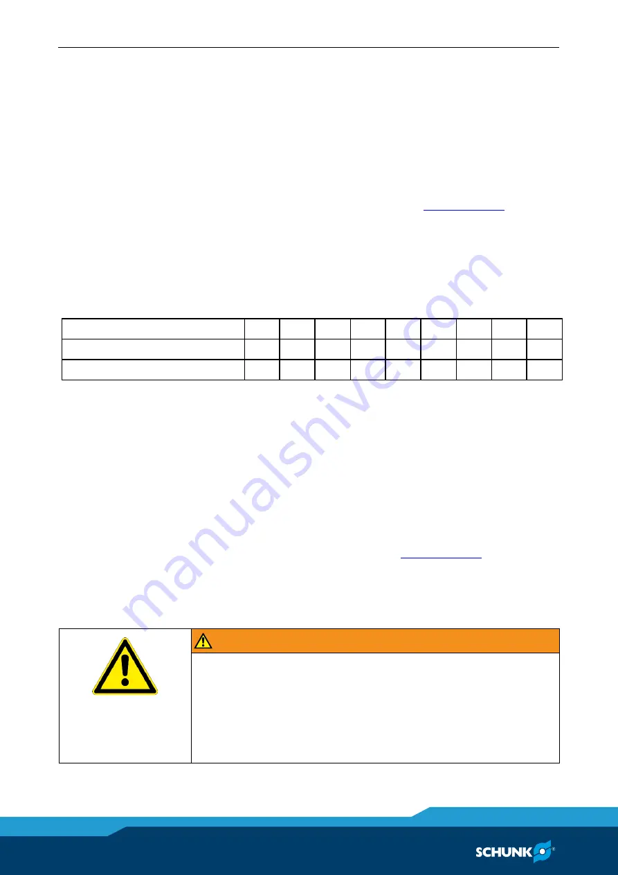
The following table shows the maximum attainable radial and axial
run-out tolerances:
Chuck size
190
225
250
315
400
500
630
800
1000
max. radial run-out error [mm] 0.02 0.02 0.03 0.03 0.04 0.05 0.06 0.08 0.10
max. axial run-out error [mm]
0.02 0.02 0.02 0.03 0.04 0.04 0.04 0.05 0.06
Replacement of jaws
When changing the top jaws, the serration must be cleaned.
Chuck jaws for maximum clamping repeat accuracy must be
turned or ground in the lathe chuck under clamping pressure.
When turning or grinding, ensure that the turning ring or turning
pin is clamped
by the top jaws
and not by the base jaws.
Tighten jaw mounting screws (screw quality 12.9) to specified
torque (see "Screw torques" chapter"
Tighten the mounting screws of the top jaws with a torque
wrench. Never tighten the Allen key with an extension pipe or by
hitting it with a hammer.
WARNING
If the workpiece is clamped at the end of the base jaw stroke,
this poses the risk that the entire clamping force is not
transferred onto the workpiece.
Risk of injury due to loss of workpiece.
•
Always clamp the workpiece at the middle of the base jaw
stroke.
5.4


