


11
Montage- und Betriebsanleitung für
Kleiner Großhub-Greifer Type KGG 80
Assembly and Operating Manual for
Small Gripper with large stroke Type KGG 80
38
38
22
37
21
47
47
38
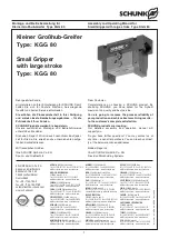
Einschubrichtung
für die Näherungsschalter
Plug.in direction
for the proximity switches
Näherungsschalter
1
(Schaltfläche zeigt nach oben)
Proximity switch
1
(switching area shows upside)
Näherungsschalter
2
(Schaltfläche zeigt nach unten)
Proximity switch
2
(switching area shows downside)
Greifer geschlossen:
1. Stellen Sie die Greiferfinger in Stellung »ZU«.
2. Schieben Sie den Näherungsschalter
1
vorsichtig mit der
Schaltfläche nach oben in den unteren Teil der Halterung
(Pos. 21) und fixieren Sie ihn mit den Schrauben (Pos. 47) im
Langloch.
3. Schließen Sie den Näherungsschalter
1
an.
4. Schieben Sie den Näherungsschalter
1
im Langloch nach
vorne. Wenn der Näherungsschalter bedämpft wird, schieben
Sie ihn noch ca. 0,5 mm weiter in dieselbe Richtung.
5. Ziehen Sie die Schrauben (Pos. 47) mit Gefühl an.
6. Testen Sie die Funktion, indem Sie den Greifer öffnen und
schließen.
Greifer geöffnet:
1. Stellen Sie die Greiferfinger in Stellung »AUF«.
2. Schieben Sie den Näherungsschalter
2
vorsichtig mit der
Schaltfläche nach unten in den oberen Teil der Halterung
(Pos. 21) und fixieren Sie ihn mit den Schrauben (Pos. 47) im
Langloch.
3. Schließen Sie den Näherungsschalter
2
an.
4. Schieben Sie den Näherungsschalter
2
im Langloch nach
vorne. Wenn der Näherungsschalter bedämpft wird, schieben
Sie ihn noch ca. 2 mm weiter in dieselbe Richtung.
5. Ziehen Sie die Schrauben (Pos. 47) mit Gefühl an.
6. Testen Sie die Funktion, indem Sie den Greifer schließen und
öffnen.
Gripper closed:
1. Put the gripper fingers into position “CLOSED”.
2. Carefully move the proximity switch
1
with ist switching area
showing upside into the bottom part of the bracket (item 21)
and fix it with the screws (item 47) in the long hole.
3. Connect the proximity switch
1
.
4. Move the proximity switch
1
inside the long hole to the front
side. When the proximity switch is actuated, move it appr.
another 0,5 mm into the same direction.
5. Slowly thighten the screws (item 47).
6. Control function by closing and opening the gripper.
Gripper opened:
1. Put the gripper fingers into position “OPEN”.
2. Carefully move the proximity switch
2
with its switching area
showing down into the upper part of the bracket (item 21) and
fix it with the screws (item 47) in the long hole.
3. Connect the proximity switch
2
.
4. Move the proximity switch
2
inside the long hole to the front
side. When the proximity switch is actuated, move it appr.
another 2 mm into the same direction.
5. Slowly thighten the screws (item 47).
6. Control function by closing and opening the gripper.
Montage
und
Einstellung
der
induktiven
Näherungsschalter
HINWEIS:
Die Näherungsschalter sind Zubehör und müssen gesondert
bestellt werden. Der Greifer ist von SCHUNK für den Einsatz von
Näherungsschaltern vorbereitet (siehe Abbildung).
Assembly and adjustment of the inductive
proximity switches
NOTE:
Proximity switches are accessories and have to be ordered sepa-
rately. SCHUNK equips the gripper with brackets and is therefore
ready for use with proximity switches (see illustration).


