background image

Assembly

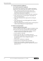
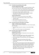
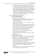
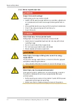
6 Assembly

6.1 Installing and connecting

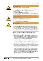
 DANGER

Risk of injury due to electric shock!

Contact with live parts can result in death.

The electrical connections may only be made by qualified
electricians.

Secure danger zone with suitable protective measures.

Only connect load and logic voltage of the motor at the end of
assembly.

Only connect voltage supply of the actuation after leaving the
danger zone.

 WARNING

Risk of injury due to unexpected movements!

If the power supply is switched on or residual energy remains in
the system, components can move unexpectedly and cause
serious injuries.

Before starting any work on the product: Switch off the power
supply and secure against restarting.

Make sure, that no residual energy remains in the system.

 WARNING

Risk of injury due to improperly carried out assembly!

Improperly carried out assembly work can lead to severe injuries
and property damage.

Before beginning work, ensure sufficient assembly clearance.

Secure components from falling down or over.

Ensure that all work has been carried out in accordance with
the specifications in these instructions.

Observe tightening torques.

19

01.00 | ELG | Assembly and Operating Manual | en | 1527393

Summary of Contents for ELG 120

Page 1: ...Translation of the original manual Assembly and Operating Manual ELG Configurable electric 2 finger long stroke gripper...

Page 2: ...on 01 00 15 09 2022 en Dear Customer thank you for trusting our products and our family owned company the leading technology supplier of robots and production machines Our team is always available to...

Page 3: ...11 Fundamental dangers 11 2 11 1 Protection during handling and assembly 12 2 11 2 Protection during commissioning and operation 12 2 11 3 Protection against dangerous movements 12 2 11 4 Protection a...

Page 4: ...ce 32 9 1 Observation of the maintenance and lubrication intervals 32 9 2 Lubricants Lubrication points basic lubrication 32 9 3 Lubricate product 33 9 4 Servomotor brake maintenance 33 10 Disassembly...

Page 5: ...nts listed under 1 1 2 6 are applicable NOTE The illustrations in this manual are intended to provide a basic understanding and may deviate from the actual version 1 1 1 Presentation of Warning Labels...

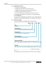
Page 6: ...d can be downloaded from the manufacturer s website 1 1 3 Sizes and variants This manual applies to the following sizes and variants ELG 75 Size 30 75 120 Stroke per jaw 100 mm 400 mm freely selectabl...

Page 7: ...y A cycle consists of a complete gripping process Open gripper and Close gripper 1 3 Scope of delivery The scope of delivery includes Configurable electric 2 finger long stroke gripper ELG in the vers...

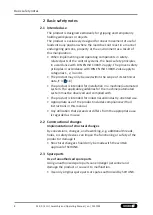
Page 8: ...f its technical data 3 16 The product is intended for installation in a machine automated system The applicable guidelines for the machine automated system must be observed and complied with The produ...

Page 9: ...s and significant property damage All work may only be performed by qualified personnel Before working with the product the personnel must have read and understood the complete assembly and operating...

Page 10: ...les when handling hazardous substances Wear close fitting protective clothing and also wear long hair in a hairnet when dealing with moving components 2 8 Notes on safe operation Incorrect handling of...

Page 11: ...ately trained personnel to rectify the malfunction Do not recommission the product until the malfunction has been rectified Test the product after a malfunction to establish whether it still functions...

Page 12: ...ejected components Falling and violently ejected components can cause serious injuries and even death Take appropriate protective measures to secure the danger zone Never step into the danger zone du...

Page 13: ...ables switch off the power supply and check that the cables are free of voltage Secure the power supply against being switched on again Before switching on the product check that the protective earth...

Page 14: ...pended loads and do not step within their swiveling range Never move loads without supervision Do not leave suspended loads unattended Wear suitable protective equipment WARNING Risk of injury from ob...

Page 15: ...lds Magnetic and electromagnetic fields can lead to serious injuries Persons with pace makers metal implants metal shards or hearing aids require the consent of a physician before entering areas in wh...

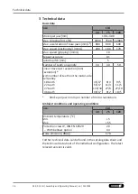
Page 16: ...avel per revolution mm revolution with number of teeth on the motor side belt pulley 18 teeth 22 teeth 27 teeth 36 teeth 45 17 55 17 135 34 90 17 9 4 11 4 27 8 9 2 9 5 11 5 27 10 18 5 Stroke per jaw i...

Page 17: ...er with lightweight profile rail guide and adaptable servo motor Two ball screw spindle drives which move the base jaw are driven by one or two servo motors via a toothed belt Synchronous version One...

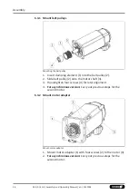
Page 18: ...y fall down and cause serious injuries Secure the product with adequately sized aids Wear suitable protective clothing 1 Fasten eye bolts to the designated threads through holes 1 provided for this pu...

Page 19: ...on or residual energy remains in the system components can move unexpectedly and cause serious injuries Before starting any work on the product Switch off the power supply and secure against restartin...

Page 20: ...n elements adapter plates 3 Secure the gripper fingers to the base jaws 6 2 1 20 Observe the maximal tightening torque admissible screw in depth and if necessary strength class 4 Connect servo motor e...

Page 21: ...for mounting screws M10 M12 M16 Required number of screws piece 12 10 Mounting screws according to standard DIN EN ISO 4762 Mounting screw strength class 12 9 Max tightening torque Nm 85 150 360 2 Cy...

Page 22: ...rd DIN EN ISO 4762 Mounting screw strength class 12 9 Max tightening torque Nm 85 150 360 3 Cylindrical pin mm 8 12 Number of cylindrical pins required piece 2 1 Remove screws 2 and cylindrical pin 3...

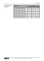
Page 23: ...X X AKO EN ISO 9409 1 100 6 M8 X X X AKO EN ISO 9409 1 125 6 M10 X X X AKO EN ISO 9409 1 160 6 M10 X X X AKO EN ISO 9409 1 160 11 M12 X X X AKO EN ISO 9409 1 200 12 M12 X X X AKO EN ISO 9409 1 200 12...

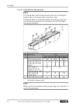
Page 24: ...e distance between the mounting screws and the finger mounting is sufficient Connections at the base jaws Item Mounting ELG 30 1 30 2 75 1 75 2 120 1 120 2 1 Thread in base jaws M8 M10 M12 Required nu...

Page 25: ...imum electrical energy values see servomotor operating manual Grounding thread If necessary connect the grounding cable to the ground connection 1 6 3 Mount servo motors When selecting a suitable moto...

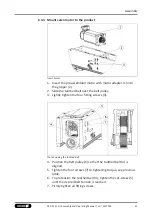
Page 26: ...pulley 2 2 Slide belt pulley 2 onto the motor shaft 3 3 Hand tighten four screws 4 for later alignment 4 For asynchronous version Carry out previous steps for the second motor 6 3 2 Mount motor adapt...

Page 27: ...ighten the four fitting screws 3 Pre tensioning the toothed belt 4 Position the belt pulley 6 so that the toothed belt 4 is aligned 5 Tighten the four screws 7 to tightening torque see previous table...

Page 28: ...ound connection 6 2 2 25 9 For asynchronous version Carry out previous steps for the second motor Shaft diameter mm Tightening torque Nm 9 11 1 14 1 2 19 3 24 7 5 6 3 4 Mount the covers NOTE Cover pla...

Page 29: ...ing force precisely CAUTION Material damage caused by excessive running speed Components might become damaged due to impacts if the workpiece collides or in the end stop Observe maximum permissible ru...

Page 30: ...ipping Position and size of the workpiece not known The precise position of the gripping position e g owing to large component tolerances or an inaccurate storage place in the predecessor process then...

Page 31: ...tauschen Actuation defective Check actuation hardware and software Component part defective Replace component or send it to SCHUNK for repair 8 2 The gripping force drops Possible cause Corrective ac...

Page 32: ...h as chips and debris Oil or grease external steel parts 9 2 Lubricants Lubrication points basic lubrication WARNING Risk of injury due to contact with lubricants Lubricant may cause irritation and al...

Page 33: ...ts 9 3 Lubricate product WARNING Risk of injury due to moving parts When moving the gripper fingers body parts may get squashed hit causing severe injuries Do not interfere with moving parts during op...

Page 34: ...unexpectedly and cause serious injuries Before starting any work on the product Switch off the power supply and secure against restarting Make sure that no residual energy remains in the system Discon...

Page 35: ...ELG The partly completed machine may not be put into operation until conformity of the machine into which the partly completed machine is to be installed with the provisions of the Machinery Directiv...

Page 36: ...overall machine Fulfilled for the scope of the partly completed machine Not relevant 1 1 Essential Requirements 1 1 1 Definitions X 1 1 2 Principles of safety integration X 1 1 3 Materials and product...

Page 37: ...tics of guards and protective devices 1 4 1 General requirements X 1 4 2 Special requirements for guards X 1 4 2 1 Fixed guards X 1 4 2 2 Interlocking movable guards X 1 4 2 3 Adjustable guards restri...

Page 38: ...n from Annex 1 is to be supplemented from here forward 2 Supplementary essential health and safety requirements for certain categories of machinery X 2 1 Foodstuffs machinery and machinery for cosmeti...

Page 39: ......
Page 40: ...Clamping and gripping technology Bahnhofstr 106 134 D 74348 Lauffen Neckar Tel 49 7133 103 0 Fax 49 7133 103 2399 info de schunk com schunk com Folgen Sie uns I Follow us 09 2022 2022 SCHUNK GmbH Co K...

Reviews: