


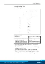
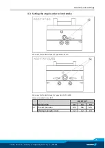
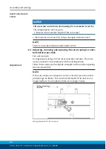


Assembly and settings
14
03.00 | AGE-F-XY | Assembly and Operating Manual | en | 389002
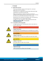
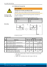
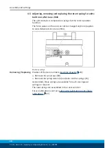
4.2 Mechanical connection
WARNING
Breakage due to faulty assembly possible!
Observe max. screw-in depth on robot-side and on tool-side.
Evenness of the
mounting surface
The values apply to the whole mounting surface to which the
product is mounted.
Requirements for evenness of the mounting surface (Dimensions in mm)
Edge length
Permissible unevenness
< 100
< 0.02
> 100
< 0.05
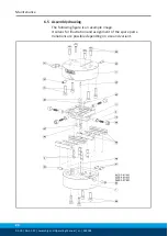
Mounting
Possibilities of assembly
Mounting material
Item
Mounting
AGE-F-XY
31
40
63
80
Y
Thread diameter and
max. screw-in depth Y tool-side [mm]
M2,5x7
M3x8
M4x8
M5/
M6x10
X
Thread diameter and
max. screw-in depth X tool-side [mm]
M3x5
M3x5 M5/M6x9 M8x12/2
0
Z
Max. srew-in depth Z, robot-side [mm]
6
6
9
13
31
DIN 4762 cylindrical screw
Tightening torque [Nm]
M2,5
0,75
M3
1,27
M5
5,9
M8
24,6
Diameter of the cylindrical pins
for mounting the module [mm]
Ø2
Ø3
Ø4
Ø6
Ø
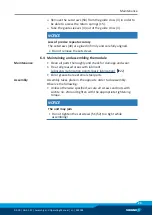
Use two cylindrical pins to fasten the module via the provided
fixing holes.
Ø
Tighten the mounting screws (31) using an Allen key.


