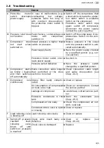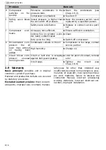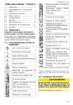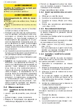
II/2
UNM STS/STL
GB
• Be calm and focused and ensure proper
operation.
• Protect yourself and other persons, ani-
mals, property, and the environment by
taking the necessary protective measures
and being trained in use of the devices to
prevent harm to your health, property
damage, financial loss, environmental
harm or risk of accident.
• Repairs may be carried out only by
Schneider Druckluft GmbH or its approved
service partners.
• Observe the Instruction Manual for ves-
sels!
•
Prohibited:
Manipulation, inappropriate
use, temporary repairs, use of other ener-
gy sources, removal or use of damaged
safety equipment, operating a leaking or
malfunctioning system, use of non-original
spare parts, exceeding the specified per-
missible working pressure, working with-
out protective clothing, maintaining /
repairing or leaving a pressurised machine
unattended, using other / unsuitable lubri-
cants, smoking, naked flames.
2.4 Commissioning
2.4.1 Conditions at the installation lo-
cation
• Rooms: as dust-free as possible, dry, well
ventilated.
• Installation surface: flat, horizontal.
• Keep heat dissipating devices and lines
away from the compressor.
• When installing the vessel, make sure that
all sides can be viewed clearly and internal
checks made unhindered.
• Type plate easily visible.
2.4.2 Before first use
1. Carry out a visual inspection.
2. Check the electrical connection.
3. Check the oil level (see Chap. 2.6.4).
4. Attach the rubber dampers (see Chap.
2.4.5).
2.4.3 Electrical connection
• The mains voltage must match that speci-
fied on the rating plate.
• Electric protection according to technical
data.
• Install the main switch and connection ca-
ble (not included in scope of supply)!
L
Cable: cross section: min. 2.5 mm²; max.
cable length:10 m.
With compressors from 5.5 kW, install a
star-delta switch instead of a main switch.
2.4.4 Checking / changing the rota-
tion direction
Perform a rotation direction check at the "ex-
ternal" three-phase current source before
starting operation.
1. Connect the compressor to the mains
power supply.
2. Switch on the compressor at the ON/OFF
switch.
3. Note the rotation direction of the fan
wheel.
4. If the rotation direction does not corre-
spond to the direction of the arrow on the
belt guard grating, change the direction.
5. Switch off the compressor at the ON/OFF
switch.
1. Interrupt the power supply to the main
switch.
Have a trained and qualified electrician per-
form the following tasks:
1. Change over the phases.
2. Check the rotation direction. (see above)
3. If direction of rotation has not changed:
contact service partner.
2.4.5 Attach rubber dampers
Lift compressor with crane. Select lifting
equipment capable of supporting the weight
of the compressor. See technical data.
1. Guide a suitable loading strap or chain
through the console. Do not damage any
compressor components.
2. Screw rubber dampers (item 23) to the
feet of the vessel. Do not forget to insert
washers! Tighten nuts to 80 Nm.
2.5 Operation
L
Do not overload the compressor: do not
exceed the max. number of switching cy-
cles and the ratio of operating time to
standstill!
WARNING
Damage to the connexion cable!
X
Protect it from sharp edges, oil and heat!
X
Grasp the plug and unplug it from the
power outlet!
Summary of Contents for UNM STS 1000-10-270
Page 10: ...2a 3a 4a 7a 7b 5a SB 2b 2c S 6a...
Page 55: ......


