background image

 FSP

 II/ 9

GB

L

• Protect yourself and other persons, ani-

mals, property, and the environment by
taking the necessary protective measures
and being trained in use of the devices to
prevent harm to your health, property
damage, financial loss, environmental
harm or risk of accident.

• Be calm and focused and ensure proper

operation.

• Repairs may be carried out only by

Schneider Druckluft GmbH or its approved
service partners.

Prohibited:

 manipulation, inappropriate

use, temporary repairs, use of other ener-
gy sources, removal or use of damaged
safety equipment, operating a leaking or
malfunctioning system, use of non-original
spare parts, exceeding the permitted
working pressure specified (max. + 10%),
working without protective equipment,
transporting / maintaining / repairing or
leaving a pressurised machine unattended,
using other / unsuitable lubricants, smok-
ing, naked flames, removing stickers.

Prohibited:

 Using explosive or flammable

cleaning agents; disposing of leftover ma-
terials / cleaning agents incorrectly.

Prohibited:

 Use in medical / food indus-

try; incorrect processing equipment; spark
formation.

2.4

Commissioning

Before start-up:

1. Observe technical data, figures, item

numbers, intended use and safety in-
structions 

(see Instruction manual, Part 1, Chap-
ter: "Technical data" and the "Intended
use" chapter).

2. Carry out a visual inspection.
3. Do not use below 5° C.

4. Use corresponding nozzle set (item 10-

13), (Figure 3c).

5. Observe manufacturer's instructions for

paint processing.

6. Add material to paint vessel (refer to

part 1 of the operating manual).

Compressed air connection:

1. Connect a filter pressure reducer up-

stream of the filter.

2. Press the quick-action coupling of the air

hose onto the plug nipple (item 01)
(Figure 1a).

3. If necessary, use a microfilter and acti-

vated charcoal filter.

Operation

:

1. Adjust the working pressure on the filter

pressure reducer.

2. Press the trigger lever (item 02).
3. When using material pressure vessels,

observe the material / air pressure set-
ting and Part 1 of the Instruction manual
(Technical data).

4. Maintain the same distance to the

sprayed object, approx. 15-25 cm.

5. Do not move from side to side, spray

parallel to the sprayed object.

Settings:

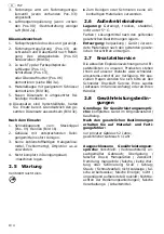
1. Round spray setting (item 04): 

turn towards the right for smaller surfac-
es, corners, edges.

2. Wide spray setting (item 04): setting for

horizontal or vertical distribution.
Turn towards the left for larger surfaces.

L

For paint spray guns with slotted nozzle,
this adjustment is unnecessary. 

3. The paint quantity is adjusted at the

paint quantity regulating valve (if
present, item 03).

4. Air quantity regulation (If present,

item 08): turn towards the right for less
air (Figure 2a).

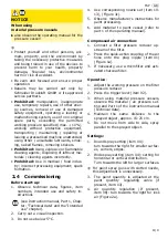
NOT

IC

E

When using 
material pressure vessels

X

also observe the operating manual for the
pressure vessel!

Summary of Contents for FSP-FP-HTE-1,3

Page 1: ...2 II 7 Notice d utilisation d origine Partie 1 I 5 Partie 2 II 13 Manual de instrucciones original Parte 1 I 7 Parte 2 II 19 Originele gebruiksaanwijzing Deel 1 I 9 Deel 2 II 25 Oryginalna instrukcja...

Page 2: ......

Page 3: ...04 01 02 06 03 05 09 11 1a 1b 2a 2b 3a 3b 3c...

Page 4: ......

Page 5: ...Inbetriebnahme Achtung Bedienungsanleitung Teil 2 lesen und beachten Achtung Ger t drucklos machen 1 1 Allgemeine Hinweise 1 1 2 Lieferumfang 1 1 3 Bestimmungsgem e Verwen dung 1 1 4 Technische Daten...

Page 6: ...mt DIN EN ISO 12100 DIN EN 1953 BGR 500 DIN 31000 DIN 31001 1 94 9 EG 98 37 EG bis 28 12 2009 2006 42 EG ab 29 12 2009 i V Marco Lodni Leiter Entwicklung Versuch 08 2008 Schneider Druckluft GmbH Ferdi...

Page 7: ...g Note Read and memorise part 2 of the instruction manual Caution Depressurise the unit 1 1 General information 3 1 2 Scope of delivery 3 1 3 Conventional use 3 1 4 Technical data 3 1 5 Components 3 1...

Page 8: ...standards DIN EN ISO 12100 DIN EN 1953 BGR 500 DIN 31000 DIN 31001 1 94 9 EC 98 37 EC before 28 12 2009 2006 42 EC after 29 12 2009 pp Marco Lodni Head of Development Testing 08 2008 Schneider Drucklu...

Page 9: ...e en service Attention consulter et respecter les consignes du mode d emploi partie 2 Attention Mettez l appareil hors pression 1 1 G n ralit s 5 1 2 El ments fournis 5 1 3 Consignes d utilisation 5 1...

Page 10: ...0 DIN EN 1953 BGR 500 DIN 31000 DIN 31001 1 94 9 CE 98 37 CE jusqu au 28 12 2009 2006 42 CE partir du 29 12 2009 p p Marco Lodni Responsable D veloppement Essais 08 2008 Schneider Druckluft GmbH Ferdi...

Page 11: ...y observar el manual de instrucciones parte 2 Atenci n despresurizar el aparato 1 1 Indicaciones generales 7 1 2 Suministro 7 1 3 Uso previsto 7 1 4 Datos t cnicos 7 1 5 Composici n 7 1 6 Puesta en s...

Page 12: ...nor mas DIN EN ISO 12100 DIN EN 1953 BGR 500 DIN 31000 DIN 31001 1 94 9 CE 98 37 CE hasta 28 12 2009 2006 42 CE desde 29 12 2009 p p Marco Lodni Director de desarrollo y ensayo 08 2008 Schneider Druck...

Page 13: ...Inbedrijfname Let op gebruiksaanwijzing deel 2 lezen en in acht nemen Let op apparaat drukloos maken 1 1 Algemene aanwijzingen 9 1 2 Leveringsomvang 9 1 3 Toepassing conform de bepalin gen 9 1 4 Tech...

Page 14: ...DIN EN ISO 12100 DIN EN 1953 BGR 500 DIN 31000 DIN 31001 1 94 9 EG 98 37 EG tot 28 12 2009 2006 42 EG vanaf 29 12 2009 bij volmacht Marco Lodni Leider Ontwikkeling Proefneming 08 2008 Schneider Druckl...

Page 15: ...stosowa si do cz i 2 instrukcji obs ugi Uwaga Urz dzenie pozbawione ci nienia 1 1 Wskaz wki og lne 11 1 2 Zakres dostawy 11 1 3 U ytkowanie zgodne z przeznaczeniem 11 1 4 Dane techniczne 11 1 5 Konst...

Page 16: ...ami DIN EN ISO 12100 DIN EN 1953 BGR 500 DIN 31000 DIN 31001 1 94 9 WE 98 37 WE do 28 12 2009 2006 42 WE od 29 12 2009 z up Marco Lodni Kierownik Dzia u Rozwoju i Bada 08 2008 Schneider Druckluft GmbH...

Page 17: ...8 I 13 RUS 1 1 1 2 1 2 1 3 1 4 1 5 1 6 2 1 1 13 1 2 13 1 3 13 1 4 13 1 5 13 1 6 13 1 7 14 130 200 M 2 P 1 2 600 1 3 1 5 1 8 d 93 8 Lpa 1 DIN 45 635 20 77 6 A L 10 9 5 40 C x x 170 x 105 x 335 0 54 01...

Page 18: ...100 DIN EN 1953 BGR 500 DIN 31000 DIN 31001 1 94 9 EG 98 37 EG 28 12 2009 2006 42 EG 29 12 2009 08 2008 Schneider Druckluft GmbH Ferdinand Lassalle Str 43 72770 Reutlingen FSP FP HTE 1 3 G006072 FSP F...

Page 19: ...igte kondensat und lfreie Druckluft Leistungsgr e Kompressor ma gebend ist der Luftverbrauch des Ger tes Werkzeu ges 2 2 Symbole Achtung Schenken Sie diesen Symbolen h chste Aufmerksamkeit 2 1 Allgeme...

Page 20: ...enwechsel Farbe auf nachf llen gilt X Druckluftanschluss trennen X Ger t drucklos machen WARNUNG Ger t kann verschieden Temperaturen annehmen X Typspezifischen Temperaturbereich des Arbeitsmaterials s...

Page 21: ...ng und Sicherheitshinweise beachten siehe auch Bedienungsanleitung Teil 1 Kapitel Technische Daten und Kapitel Bestimmungsgem e Verwendung 2 Sichtpr fung vornehmen 3 Nicht unter 5 C anwenden 4 Entspre...

Page 22: ...rwenden 2 6 Au erbetriebnahme Lagerung Gereinigt trocken staubfrei nicht unter 5 C Farben L sungsmittel nach den geltenden gesetzlichen Bestimmungen lagern Entsorgung Verpackung Ger t verwen dete Mate...

Page 23: ...B Spritzbild nur teil weise vorhanden Luftkappe Pos 11 ver schmutzt oder besch digt X Reinigen siehe Kapitel 4 5 oder kompletten D sensatz aus tauschen siehe Bild 3a c Farbe klebt an der D se oder Tei...

Page 24: ...Viskosit t erh hen D sensatz mit kleinerem Durchmesser ver wenden Kompressorleistung zu klein X Andere Leistungsgr e verwenden Strahlbreite zu gro X Strahlbreite verringern Pos 4 E Konzentrierte Mate...

Page 25: ...sed air that is free of condensate and oil Powerful compressor the air consumption of the machine tool is decisive 2 2 Symbols Important Pay particular attention to these symbols 2 1 General informati...

Page 26: ...ing refilling paint X Disconnect the compressed air connection X Depressurise the unit WARNING The device can take on different tem peratures X Observe the type specific temperature range of the work...

Page 27: ...he Intended use chapter 2 Carry out a visual inspection 3 Do not use below 5 C 4 Use corresponding nozzle set item 10 13 Figure 3c 5 Observe manufacturer s instructions for paint processing 6 Add mate...

Page 28: ...tore paints solvents according to applica ble legal provisions Disposal Dispose of the packaging device materials used according to applicable legal regulations 2 7 Spare parts service Visit our websi...

Page 29: ...3a c Nozzle needle is damaged X Replace the complete nozzle set item 10 11 12 or 13 C Irregular paint application with drip formation Nozzle dirty or damaged X Clean see Chapter 4 5 or re place comple...

Page 30: ...nozzle set Reduce paint quantity item 03 Decrease material pressure item 18 Working pressure flow pres sure too low X Increase working pressure flow pressure Observe maximum working pressure Viscosity...

Page 31: ...e compatible air comprim propre exempt d huile et de condensats unique ment Puissance du compresseur la consomma tion d air de l appareil l outil est d terminan te 2 2 Pictogrammes Attention en pr sen...

Page 32: ...proscrite AVERTISSEMENT Fonctionnement bruyant X Porter une protection auditive AVERTISSEMENT Le tuyau air comprim fouette lors de l ouverture du raccord pompier X Maintenir le tuyau air comprim AVER...

Page 33: ...ts inflammables ou explosifs l limination non conforme des r sidus d tergents Sont interdits les utilisations en milieu m dical agro alimentaire l utilisation de produits inad quats les formations d t...

Page 34: ...ner la g chette rep 02 puis retirer l aiguille d injec teur fig 3a 3 En fonction du type de pistolet peintu re D monter le capuchon d air rep 11 la tuy re fente rep 13 ou l crou chapeau rep 06 cf fig...

Page 35: ...te que le r servoir soit bien la verticale Capuchon de peinture des serr ou endommag X Visser le capuchon de peinture fond ou remplacer le jeu de bu ses rep 10 11 12 ou 13 dans son ensemble cf fig 3a...

Page 36: ...iliser un jeu de buses de plus petit dia m tre Performances du compresseur insuffisantes X S lectionner une puissance adapt e Jet trop large X R duire la largeur du jet rep 4 E Quantit de produit plus...

Page 37: ...camente aire compri mido limpio sin condensaci n ni aceite Capacidad del compresor el consumo de aire del aparato de la herramienta es deter minante 2 2 S mbolos Atenci n preste la m xima atenci n a l...

Page 38: ...rimido ADVERTENCIA En los trabajos de mantenimiento reparaci n cambio de boquilla llenado de pintura X Desconectar la conexi n neum tica X Despresurizar el aparato ADVERTENCIA El aparato puede soporta...

Page 39: ...n meros de posici n el uso previsto y las indicaciones de seguridad v ase tambi n el manual de instruc ciones parte 1 cap tulo Datos t cni cos y cap tulo Uso previsto 2 Efectuar un examen visual 3 No...

Page 40: ...o clo ruro de etilo o similares 4 No introducir completamente en un ba o una m quina de limpieza 2 5 Mantenimiento X No utilizar materiales que contengan silico na para la limpieza o la lubricaci n 2...

Page 41: ...aplicada del chorro de pro yecci n es parcial La caperuza para el aire pos 11 est sucia o deterio rada X Limpiar v ase el cap tulo 4 5 o sustituir todo el juego de boqui llas v ase la fig 3a c La pin...

Page 42: ...un juego de tobera de menor di metro Potencia del compresor insufi ciente X Aumentar la potencia Ancho de chorro excesivo X Reducir el ancho de chorro pos 4 E El material se acu mula de forma con cen...

Page 43: ...condensaat en olievrije perslucht Vermogen compressor beslissend is het luchtverbruik van het apparaat gereed schap 2 2 Symbolen Let op Schenk de hoogste oplettendheid aan deze symbolen 2 1 Algemene a...

Page 44: ...sthouden WAARSCHUWING Bij onderhouds en reparatiewerkzaam heden sproeierwisseling en bij vullen van verf geldt X Persluchtaansluiting losmaken X Apparaat drukloos maken WAARSCHUWING Apparaat kan versc...

Page 45: ...edrijfstelling 1 Technische gegevens afbeeldingen po sitienummers gebruik conform de bepa lingen en veiligheidsinstructies in acht nemen zie ook gebruiksaanwijzing deel 1 hoofdstuk Technische gegevens...

Page 46: ...oormethyl ethyleen chloor etc gebruiken 4 Niet geheel in reinigingsbad machines leggen 2 5 Onderhoud X Voor het reinigen of smeren geen silicone houdend materiaal gebruiken 2 6 Buitenbedrijfstelling O...

Page 47: ...igd X Reinigen zie hoofdstuk 4 5 of complete sproeierset vervangen zie afbeelding 3a c Sproeiernaald beschadigd X Complete sproeierset pos 10 11 12 resp 13 vervangen C Onregelmatig kleur beeld met dru...

Page 48: ...aal aangebracht X Kleinere sproeierset gebruiken Verfhoeveelheid beperken pos 03 Materiaaldruk verlagen pos 18 Werkdruk continudruk te gering X Werkdruk continudruk verho gen Maximale werkdruk in acht...

Page 49: ...zone spr one powietrze kt re nie zawiera kondensatu ani oleju Wydajno spr arki okre lana w oparciu o pob r powietrza przez urz dzenie narz dzie 2 2 Symbole Uwaga Symbole te nale y traktowa z najwy sz...

Page 50: ...w spr onego powietrza OSTRZE ENIE Przy pracach konserwacyjnych naprawczych wymianie dyszy nape nianiu uzupe nianiu farby obowi zuj nast puj ce zasady X Od czy przy cze spr onego powietrza X Urz dzeni...

Page 51: ...tek materia w rodk w czyszcz cych Zakaz stosowania do lek w rodk w spo ywczych nieprawid owe rodki przetwarzania iskrzenie 2 4 Uruchamianie Przed uruchomieniem 1 Nale y przestrzega danych technicznych...

Page 52: ...now poz 13 lub nakr tk ko pakow poz 06 patrz rys 3a 4 Zdemontowa pokryw materia ow za pomoc odpowiedniego klucza rys 3b 5 Zamontowa nowy zestaw dysz w odwrotnej kolejno ci L Zestawy dysz s cz ciami po...

Page 53: ...ie nieprawidowych rodk w eksploatacyjnych 2 9 Usuwanie usterek Nale y przestrzega zalece dotycz cych bezpiecze stwa oraz konserwacji Usterka Przyczyna Spos b usuwania A Strumie farby jest przerywany l...

Page 54: ...czelinow poz 13 lub wymieni zestaw dysz Pokrywa powietrza i dysza s zatkane farb X Czyszczenie patrz rozdzia 4 5 lub wymiana ca ego zestawu dysz poz 10 11 12 wzgl dnie 13 patrz rys 3a c Zbyt ma a lepk...

Page 55: ...FSP II 37 RUS 2 2 1 0 X Y 1 1 _ _ 2 2 2 1 37 2 2 37 2 3 38 2 4 40 2 5 41 2 6 41 2 7 41 2 8 41 2 9 42 Q XY XY YQ Y _ X Q Q Y Lichamelijk letsel of dood van de bediener...

Page 56: ...II 38 FSP RUS 2 3 X X 1 X X X 0 20 X X _ X X X X...

Page 57: ...FSP II 39 RUS L Schneider Druckluft GmbH 10 X X X X 0 X X X X X...

Page 58: ...II 40 FSP RUS 2 4 0 0 1 1 2 3 5 C 4 10 13 3c 5 6 X 1 1 2 01 1a 3 X 1 2 02 3 1 4 15 25 5 1 _ 04 2 04 L 3 _ 03 4 08 2a 1 2 03 02 3a 3 11 13 06 3a 4 3b 5 L _ 3c...

Page 59: ...FSP II 41 RUS 1 01 1b 2 3 4 2 5 _ X 2 6 www schneider airsystems com td Schneider Druckluft 2 7 0 5 C 2 8 2 1...

Page 60: ...II 42 FSP RUS 2 9 Q A X X X 10 11 12 13 3a c X X 09 14 X 4 5 B X 11 X 4 5 3a c _ X 4 5 3a c X X 10 11 12 13 C X X 4 5 10 11 12 13 3a c X X 18 X 11 X...

Page 61: ...FSP II 43 RUS 1 D X X X 13 X 4 5 10 11 12 13 3a c X X X 4 E _ X 03 18 X X 18 F X X 4 5 10 11 12 13 3a c Q...

Page 62: ...090 RASZYN Janki k W wy 48 22 711 41 61 48 22 720 11 00 E Mail tooltechnic_poland festo com Rossija Tooltechnic Systems 13 111250 007 495 72195 85 007 495 361 22 09 E Mail info tooltechnic ru Schweiz...

Reviews: