background image

 FSP

II/ 21

E

L

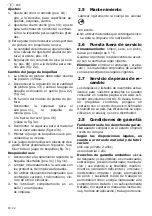
• Proteja su propia integridad así como al

resto de personas, los animales, los mate-
riales y al medio ambiente adoptando las
medidas de protección y precaución nece-
sarias, la instrucción sobre los aparatos y
la prevención sanitaria con objeto de evitar
daños a la salud, daños materiales, daños
medioambientales y posibles accidentes.

• Trabajar descansado y concentrado para

asegurar un funcionamiento correcto.

• Las reparaciones sólo pueden ser realiza-

das por Schneider Druckluft GmbH o em-
presas colaboradoras.

Prohibido:

 manipulaciones; finalidades

distintas; reparaciones de emergencia;
otras fuentes de energía; eliminar disposi-
tivos de seguridad o dañarlos; uso en caso
de falta de estanqueidad o anomalías en el
funcionamiento; usar piezas no originales;
sobrepasar la presión de trabajo (máx.
+10 %) admisible indicada; trabajar sin
equipo de protección; transportar, mante-
ner, reparar o dejar sin vigilancia el aparato

bajo presión; utilizar otros lubricantes no
permitidos; fumar; fuego abierto; retirar
las etiquetas adhesivas.

Prohibido:

 utilizar productos de limpieza

explosivos o inflamables; eliminar inco-
rrectamente los restos de material/produc-
tos de limpieza.

Prohibido:

 aplicación en el sector farma-

cológico/alimenticio; medios de aplicación
erróneos; formación de chispas.

2.4

Puesta en servicio

Antes de la puesta en servicio:

1. Observar los datos técnicos, las figuras,

los números de posición, el uso previsto
y las indicaciones de seguridad 

(véase también el manual de instruc-
ciones, parte 1, capítulo "Datos técni-
cos" y capítulo "Uso previsto").

2. Efectuar un examen visual.
3. No utilizar por debajo de los 5 °C.
4. Utilizar el juego de boquillas correspon-

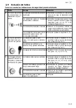
diente (pos. 10-13), (fig. 3c).

5. Observar las indicaciones del fabricante

sobre la preparación de la pintura.

6. Introducir el material en el depósito de

pintura (véase también el manual de ins-
trucciones, parte 1).

Conexión neumática:

1. Instalar un reductor de la presión del fil-

tro.

2. Presionar el acoplamiento rápido de la

manguera de aire comprimido sobre la
boquilla insertable (pos. 01) (fig. 1a).

3. En caso necesario, utilizar un filtro finísi-

mo y un filtro de carbón activo.

Funcionamiento:

1. Ajustar la presión de trabajo en el reduc-

tor de la presión del filtro.

2. Accionar el gatillo (pos. 02).
3. En caso de utilizar un depósito de aire

comprimido para material, observar el
ajuste de material/aire comprimido y el
manual de instrucciones, parte 1 (Datos
técnicos).

4. Mantener la misma distancia respecto al

objeto pulverizado, aprox. 15-25 cm.

5. No inclinar, pulverizar en paralelo al ob-

jeto pulverizado.

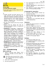
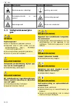
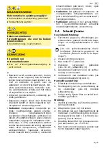
ADVERTENCIA 

¡Posibilidad de descarga electrostática!

X

¡Utilizar una manguera de aire comprimi-
do antiestática!

X

¡Conectar la manguera de aire comprimi-
do a tierra!

ATENCIÓN

¡Peligro de tropiezo!
Mangueras de aire comprimido que es-
tán tendidas sobre el suelo.

X

Evitarlas o proceder con cuidado.

A

VISO

Si se usan 
depósitos de aire comprimido para ma-
terial,

X

observar también el manual de instruccio-
nes de dichos depósitos.

Summary of Contents for FSP-FP-HTE-1,3

Page 1: ...2 II 7 Notice d utilisation d origine Partie 1 I 5 Partie 2 II 13 Manual de instrucciones original Parte 1 I 7 Parte 2 II 19 Originele gebruiksaanwijzing Deel 1 I 9 Deel 2 II 25 Oryginalna instrukcja...

Page 2: ......

Page 3: ...04 01 02 06 03 05 09 11 1a 1b 2a 2b 3a 3b 3c...

Page 4: ......

Page 5: ...Inbetriebnahme Achtung Bedienungsanleitung Teil 2 lesen und beachten Achtung Ger t drucklos machen 1 1 Allgemeine Hinweise 1 1 2 Lieferumfang 1 1 3 Bestimmungsgem e Verwen dung 1 1 4 Technische Daten...

Page 6: ...mt DIN EN ISO 12100 DIN EN 1953 BGR 500 DIN 31000 DIN 31001 1 94 9 EG 98 37 EG bis 28 12 2009 2006 42 EG ab 29 12 2009 i V Marco Lodni Leiter Entwicklung Versuch 08 2008 Schneider Druckluft GmbH Ferdi...

Page 7: ...g Note Read and memorise part 2 of the instruction manual Caution Depressurise the unit 1 1 General information 3 1 2 Scope of delivery 3 1 3 Conventional use 3 1 4 Technical data 3 1 5 Components 3 1...

Page 8: ...standards DIN EN ISO 12100 DIN EN 1953 BGR 500 DIN 31000 DIN 31001 1 94 9 EC 98 37 EC before 28 12 2009 2006 42 EC after 29 12 2009 pp Marco Lodni Head of Development Testing 08 2008 Schneider Drucklu...

Page 9: ...e en service Attention consulter et respecter les consignes du mode d emploi partie 2 Attention Mettez l appareil hors pression 1 1 G n ralit s 5 1 2 El ments fournis 5 1 3 Consignes d utilisation 5 1...

Page 10: ...0 DIN EN 1953 BGR 500 DIN 31000 DIN 31001 1 94 9 CE 98 37 CE jusqu au 28 12 2009 2006 42 CE partir du 29 12 2009 p p Marco Lodni Responsable D veloppement Essais 08 2008 Schneider Druckluft GmbH Ferdi...

Page 11: ...y observar el manual de instrucciones parte 2 Atenci n despresurizar el aparato 1 1 Indicaciones generales 7 1 2 Suministro 7 1 3 Uso previsto 7 1 4 Datos t cnicos 7 1 5 Composici n 7 1 6 Puesta en s...

Page 12: ...nor mas DIN EN ISO 12100 DIN EN 1953 BGR 500 DIN 31000 DIN 31001 1 94 9 CE 98 37 CE hasta 28 12 2009 2006 42 CE desde 29 12 2009 p p Marco Lodni Director de desarrollo y ensayo 08 2008 Schneider Druck...

Page 13: ...Inbedrijfname Let op gebruiksaanwijzing deel 2 lezen en in acht nemen Let op apparaat drukloos maken 1 1 Algemene aanwijzingen 9 1 2 Leveringsomvang 9 1 3 Toepassing conform de bepalin gen 9 1 4 Tech...

Page 14: ...DIN EN ISO 12100 DIN EN 1953 BGR 500 DIN 31000 DIN 31001 1 94 9 EG 98 37 EG tot 28 12 2009 2006 42 EG vanaf 29 12 2009 bij volmacht Marco Lodni Leider Ontwikkeling Proefneming 08 2008 Schneider Druckl...

Page 15: ...stosowa si do cz i 2 instrukcji obs ugi Uwaga Urz dzenie pozbawione ci nienia 1 1 Wskaz wki og lne 11 1 2 Zakres dostawy 11 1 3 U ytkowanie zgodne z przeznaczeniem 11 1 4 Dane techniczne 11 1 5 Konst...

Page 16: ...ami DIN EN ISO 12100 DIN EN 1953 BGR 500 DIN 31000 DIN 31001 1 94 9 WE 98 37 WE do 28 12 2009 2006 42 WE od 29 12 2009 z up Marco Lodni Kierownik Dzia u Rozwoju i Bada 08 2008 Schneider Druckluft GmbH...

Page 17: ...8 I 13 RUS 1 1 1 2 1 2 1 3 1 4 1 5 1 6 2 1 1 13 1 2 13 1 3 13 1 4 13 1 5 13 1 6 13 1 7 14 130 200 M 2 P 1 2 600 1 3 1 5 1 8 d 93 8 Lpa 1 DIN 45 635 20 77 6 A L 10 9 5 40 C x x 170 x 105 x 335 0 54 01...

Page 18: ...100 DIN EN 1953 BGR 500 DIN 31000 DIN 31001 1 94 9 EG 98 37 EG 28 12 2009 2006 42 EG 29 12 2009 08 2008 Schneider Druckluft GmbH Ferdinand Lassalle Str 43 72770 Reutlingen FSP FP HTE 1 3 G006072 FSP F...

Page 19: ...igte kondensat und lfreie Druckluft Leistungsgr e Kompressor ma gebend ist der Luftverbrauch des Ger tes Werkzeu ges 2 2 Symbole Achtung Schenken Sie diesen Symbolen h chste Aufmerksamkeit 2 1 Allgeme...

Page 20: ...enwechsel Farbe auf nachf llen gilt X Druckluftanschluss trennen X Ger t drucklos machen WARNUNG Ger t kann verschieden Temperaturen annehmen X Typspezifischen Temperaturbereich des Arbeitsmaterials s...

Page 21: ...ng und Sicherheitshinweise beachten siehe auch Bedienungsanleitung Teil 1 Kapitel Technische Daten und Kapitel Bestimmungsgem e Verwendung 2 Sichtpr fung vornehmen 3 Nicht unter 5 C anwenden 4 Entspre...

Page 22: ...rwenden 2 6 Au erbetriebnahme Lagerung Gereinigt trocken staubfrei nicht unter 5 C Farben L sungsmittel nach den geltenden gesetzlichen Bestimmungen lagern Entsorgung Verpackung Ger t verwen dete Mate...

Page 23: ...B Spritzbild nur teil weise vorhanden Luftkappe Pos 11 ver schmutzt oder besch digt X Reinigen siehe Kapitel 4 5 oder kompletten D sensatz aus tauschen siehe Bild 3a c Farbe klebt an der D se oder Tei...

Page 24: ...Viskosit t erh hen D sensatz mit kleinerem Durchmesser ver wenden Kompressorleistung zu klein X Andere Leistungsgr e verwenden Strahlbreite zu gro X Strahlbreite verringern Pos 4 E Konzentrierte Mate...

Page 25: ...sed air that is free of condensate and oil Powerful compressor the air consumption of the machine tool is decisive 2 2 Symbols Important Pay particular attention to these symbols 2 1 General informati...

Page 26: ...ing refilling paint X Disconnect the compressed air connection X Depressurise the unit WARNING The device can take on different tem peratures X Observe the type specific temperature range of the work...

Page 27: ...he Intended use chapter 2 Carry out a visual inspection 3 Do not use below 5 C 4 Use corresponding nozzle set item 10 13 Figure 3c 5 Observe manufacturer s instructions for paint processing 6 Add mate...

Page 28: ...tore paints solvents according to applica ble legal provisions Disposal Dispose of the packaging device materials used according to applicable legal regulations 2 7 Spare parts service Visit our websi...

Page 29: ...3a c Nozzle needle is damaged X Replace the complete nozzle set item 10 11 12 or 13 C Irregular paint application with drip formation Nozzle dirty or damaged X Clean see Chapter 4 5 or re place comple...

Page 30: ...nozzle set Reduce paint quantity item 03 Decrease material pressure item 18 Working pressure flow pres sure too low X Increase working pressure flow pressure Observe maximum working pressure Viscosity...

Page 31: ...e compatible air comprim propre exempt d huile et de condensats unique ment Puissance du compresseur la consomma tion d air de l appareil l outil est d terminan te 2 2 Pictogrammes Attention en pr sen...

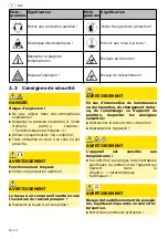
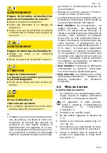
Page 32: ...proscrite AVERTISSEMENT Fonctionnement bruyant X Porter une protection auditive AVERTISSEMENT Le tuyau air comprim fouette lors de l ouverture du raccord pompier X Maintenir le tuyau air comprim AVER...

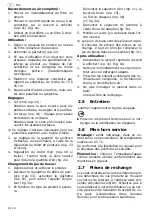
Page 33: ...ts inflammables ou explosifs l limination non conforme des r sidus d tergents Sont interdits les utilisations en milieu m dical agro alimentaire l utilisation de produits inad quats les formations d t...

Page 34: ...ner la g chette rep 02 puis retirer l aiguille d injec teur fig 3a 3 En fonction du type de pistolet peintu re D monter le capuchon d air rep 11 la tuy re fente rep 13 ou l crou chapeau rep 06 cf fig...

Page 35: ...te que le r servoir soit bien la verticale Capuchon de peinture des serr ou endommag X Visser le capuchon de peinture fond ou remplacer le jeu de bu ses rep 10 11 12 ou 13 dans son ensemble cf fig 3a...

Page 36: ...iliser un jeu de buses de plus petit dia m tre Performances du compresseur insuffisantes X S lectionner une puissance adapt e Jet trop large X R duire la largeur du jet rep 4 E Quantit de produit plus...

Page 37: ...camente aire compri mido limpio sin condensaci n ni aceite Capacidad del compresor el consumo de aire del aparato de la herramienta es deter minante 2 2 S mbolos Atenci n preste la m xima atenci n a l...

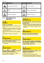
Page 38: ...rimido ADVERTENCIA En los trabajos de mantenimiento reparaci n cambio de boquilla llenado de pintura X Desconectar la conexi n neum tica X Despresurizar el aparato ADVERTENCIA El aparato puede soporta...

Page 39: ...n meros de posici n el uso previsto y las indicaciones de seguridad v ase tambi n el manual de instruc ciones parte 1 cap tulo Datos t cni cos y cap tulo Uso previsto 2 Efectuar un examen visual 3 No...

Page 40: ...o clo ruro de etilo o similares 4 No introducir completamente en un ba o una m quina de limpieza 2 5 Mantenimiento X No utilizar materiales que contengan silico na para la limpieza o la lubricaci n 2...

Page 41: ...aplicada del chorro de pro yecci n es parcial La caperuza para el aire pos 11 est sucia o deterio rada X Limpiar v ase el cap tulo 4 5 o sustituir todo el juego de boqui llas v ase la fig 3a c La pin...

Page 42: ...un juego de tobera de menor di metro Potencia del compresor insufi ciente X Aumentar la potencia Ancho de chorro excesivo X Reducir el ancho de chorro pos 4 E El material se acu mula de forma con cen...

Page 43: ...condensaat en olievrije perslucht Vermogen compressor beslissend is het luchtverbruik van het apparaat gereed schap 2 2 Symbolen Let op Schenk de hoogste oplettendheid aan deze symbolen 2 1 Algemene a...

Page 44: ...sthouden WAARSCHUWING Bij onderhouds en reparatiewerkzaam heden sproeierwisseling en bij vullen van verf geldt X Persluchtaansluiting losmaken X Apparaat drukloos maken WAARSCHUWING Apparaat kan versc...

Page 45: ...edrijfstelling 1 Technische gegevens afbeeldingen po sitienummers gebruik conform de bepa lingen en veiligheidsinstructies in acht nemen zie ook gebruiksaanwijzing deel 1 hoofdstuk Technische gegevens...

Page 46: ...oormethyl ethyleen chloor etc gebruiken 4 Niet geheel in reinigingsbad machines leggen 2 5 Onderhoud X Voor het reinigen of smeren geen silicone houdend materiaal gebruiken 2 6 Buitenbedrijfstelling O...

Page 47: ...igd X Reinigen zie hoofdstuk 4 5 of complete sproeierset vervangen zie afbeelding 3a c Sproeiernaald beschadigd X Complete sproeierset pos 10 11 12 resp 13 vervangen C Onregelmatig kleur beeld met dru...

Page 48: ...aal aangebracht X Kleinere sproeierset gebruiken Verfhoeveelheid beperken pos 03 Materiaaldruk verlagen pos 18 Werkdruk continudruk te gering X Werkdruk continudruk verho gen Maximale werkdruk in acht...

Page 49: ...zone spr one powietrze kt re nie zawiera kondensatu ani oleju Wydajno spr arki okre lana w oparciu o pob r powietrza przez urz dzenie narz dzie 2 2 Symbole Uwaga Symbole te nale y traktowa z najwy sz...

Page 50: ...w spr onego powietrza OSTRZE ENIE Przy pracach konserwacyjnych naprawczych wymianie dyszy nape nianiu uzupe nianiu farby obowi zuj nast puj ce zasady X Od czy przy cze spr onego powietrza X Urz dzeni...

Page 51: ...tek materia w rodk w czyszcz cych Zakaz stosowania do lek w rodk w spo ywczych nieprawid owe rodki przetwarzania iskrzenie 2 4 Uruchamianie Przed uruchomieniem 1 Nale y przestrzega danych technicznych...

Page 52: ...now poz 13 lub nakr tk ko pakow poz 06 patrz rys 3a 4 Zdemontowa pokryw materia ow za pomoc odpowiedniego klucza rys 3b 5 Zamontowa nowy zestaw dysz w odwrotnej kolejno ci L Zestawy dysz s cz ciami po...

Page 53: ...ie nieprawidowych rodk w eksploatacyjnych 2 9 Usuwanie usterek Nale y przestrzega zalece dotycz cych bezpiecze stwa oraz konserwacji Usterka Przyczyna Spos b usuwania A Strumie farby jest przerywany l...

Page 54: ...czelinow poz 13 lub wymieni zestaw dysz Pokrywa powietrza i dysza s zatkane farb X Czyszczenie patrz rozdzia 4 5 lub wymiana ca ego zestawu dysz poz 10 11 12 wzgl dnie 13 patrz rys 3a c Zbyt ma a lepk...

Page 55: ...FSP II 37 RUS 2 2 1 0 X Y 1 1 _ _ 2 2 2 1 37 2 2 37 2 3 38 2 4 40 2 5 41 2 6 41 2 7 41 2 8 41 2 9 42 Q XY XY YQ Y _ X Q Q Y Lichamelijk letsel of dood van de bediener...

Page 56: ...II 38 FSP RUS 2 3 X X 1 X X X 0 20 X X _ X X X X...

Page 57: ...FSP II 39 RUS L Schneider Druckluft GmbH 10 X X X X 0 X X X X X...

Page 58: ...II 40 FSP RUS 2 4 0 0 1 1 2 3 5 C 4 10 13 3c 5 6 X 1 1 2 01 1a 3 X 1 2 02 3 1 4 15 25 5 1 _ 04 2 04 L 3 _ 03 4 08 2a 1 2 03 02 3a 3 11 13 06 3a 4 3b 5 L _ 3c...

Page 59: ...FSP II 41 RUS 1 01 1b 2 3 4 2 5 _ X 2 6 www schneider airsystems com td Schneider Druckluft 2 7 0 5 C 2 8 2 1...

Page 60: ...II 42 FSP RUS 2 9 Q A X X X 10 11 12 13 3a c X X 09 14 X 4 5 B X 11 X 4 5 3a c _ X 4 5 3a c X X 10 11 12 13 C X X 4 5 10 11 12 13 3a c X X 18 X 11 X...

Page 61: ...FSP II 43 RUS 1 D X X X 13 X 4 5 10 11 12 13 3a c X X X 4 E _ X 03 18 X X 18 F X X 4 5 10 11 12 13 3a c Q...

Page 62: ...090 RASZYN Janki k W wy 48 22 711 41 61 48 22 720 11 00 E Mail tooltechnic_poland festo com Rossija Tooltechnic Systems 13 111250 007 495 72195 85 007 495 361 22 09 E Mail info tooltechnic ru Schweiz...

Reviews: