schmersal SLC 420 Operating Instructions Manual Download Page 8

8

Operating instructions

Safety light curtain/safety light grid

SLC 420

SLG 420

EN

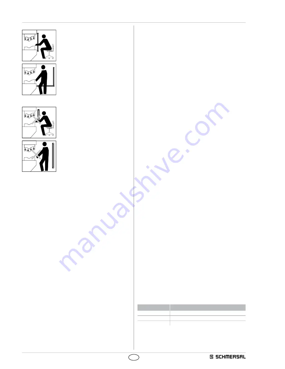
Correct installation

Hazardous machine parts can only be reached 
after passing through the protection field

Persons between the protection field and 
hazardous machine parts must be prevented 
(protection against stepping over)

Unauthorised installation

Hazardous machine parts can be reached  
without passing through the protection field

Persons between the protection field and  
hazardous machine parts is enabled

3.3  Alignment

Procedure in automatic operating mode:

1  The transmitter and the receiver must be fitted parallel to each other 

and at the same height

2  Turn the transmitter and monitor the diagnostic window of the 

receiver Fix the light curtain, when the LED OSSD ON (green) is on 

and the LED signal reception (orange) is off

3  Determine the max rotating angle to the left and to the right, at which 

the LED OSSD ON (green) is on and tighten the mounting screws in 

central position  Make sure that the LED signal reception (orange) is 

not on or flashing

3.4  Setting mode

The alignment of the sensors is carried out using the setting mode

Activating setting mode

If +24 V is on the input (pin 1, receiver) "Release restart interlock" at 

system start for at least two seconds (by pressing the button restart), 

the system changes over to the setting mode of operation

The signal strength at the receiver is indicated with the signal strength 

LED (colour orange) through light pulses The better the alignment, the 

higher the frequency of the light pulses The alignment is optimal when 

the light pulses switch over to continuous light

If there is no optical synchronisation between the transmitter and the 

receiver, a light pulse is emitted every 3 seconds The setting mode is 

ended by a system start ( +UB OFF/ON)

Additional signalling with the SLG 420 by the status light

In this mode the signal strength of the beam is signalled to the status 

indicator with the lowest value through light pulses (colour yellow)

The better the alignment, the higher the frequency of the light 

pulses The alignment is correct when the light pulses switch over to 

continuous light

3.5  Safety distance

The safety distance is the minimum distance between the protection 

field of the safety light curtain and the hazardous area The safety 

distance must be observed to ensure that the hazardous area cannot 

be reached before the hazardous movement has come to standstill

Calculation of the safety distance to EN ISO 13855

The safety distance depends on the following elements:

•  Stopping time of the machine (calculation by run-on time 

measurement)

•  Response time of the machine and the safety light curtain and the 

downstream relay (entire safety guard)

•  Approach speed

•  Resolution of the safety light curtain

•  Vertical or horizontal installation

Safety light curtain SLC 420

The safety distance for resolutions 14 mm up to 40 mm (vertical 

installation) is calculated by means of the following formula:

(1) S = K x T + C [mm]

S =  Safety distance [mm]

K =  Approach speed 2000 mm/s

T =  Total reaction time (machine run-on time, reaction time of the safety 

guard, relays, etc)

d =  Resolution of the safety light curtain

C =  additional distance depending on the resolution,  

C = 8 (d - 14) [mm]

If value S <= 500 mm after the calculation of the safety distance, then 

use this value

If the value S >= 500 mm then redetermine the distance S using an 

approach speed K of 1600 mm/s:

(2) S = 1600 mm/s * T + 8 (d - 14) [mm]

If the new value S > 500 mm, use this value as safety distance

If the new value S 

<

 500 mm, use a minimum distance of 

S = 500 mm

Example: 

Reaction time of the safety light curtain = 10 ms

Resolution of the safety light curtain = 14 mm

Stopping time of the machine = 330 ms

S = 2000 mm/s * (330 ms + 10 ms) + 8(14 mm - 14 mm)

S = 680 mm

S = > 500 mm, therefore new calculation with K = 1600 mm/s

S = 544 mm

Calculation of the safety distance for SLG 420 and SLC 420 with a 

resolution d > 40 mm

(3) S = ( 1600 mm/s * T ) + 850 mm

S =  Safety distance [mm]

T =  Stopping time of the m reaction time of the  

safety light curtain

K =  Approach speed 1600 mm/s

C =  Additional distance 850 mm

The following mounting heights must be observed:

Number of beams Mounting height above reference level in mm

2

400, 900

3

300, 700, 1100

4

300, 600, 9001200

Summary of Contents for SLC 420

Page 1: ...2 2 Special versions 3 2 3 Included in delivery 3 2 3 1 Included in delivery of SLC SLG 420 Standard 3 2 3 2 Included in delivery of SLC SLG 420 IP69K 3 2 4 Destination and use 3 2 5 Technical data 3 2 5 1 Technical data IP69K additions 3 2 6 Response time reaction time 4 2 7 Effective resolution 4 2 8 Safety classification 5 2 9 Functions 5 2 9 1 Protective mode 5 2 9 2 Restart interlock manual r...

Page 2: ...fety switchgear personal hazards or damages to machinery or plant components cannot be excluded when safety switch gear is used The relevant requirements of the standard EN ISO 13855 must be observed Only if the information described in this operating instructions manual are realised correctly the safety function and therefore the compliance with the Machinery Directive is maintained 1 7 Exclusion...

Page 3: ...ge current 3 1 mA Load capacity 200 nF Load capacity 4 2 H Admissible conduction resistance between OSSD and load 2 5 Ω Supply cable 1 Ω Contactor control EDM Input voltage HIGH inactive 17 26 4 V Input voltage LOW active 0 2 V Input current HIGH 3 10 mA Input current LOW 0 2 mA Input restart interlock Input voltage HIGH active 17 26 4 V Input voltage LOW inactive 0 2 V Input current HIGH 3 10 mA ...

Page 4: ...0 15 3 4 4 8 970 48 10 15 3 6 5 2 1050 52 20 27 3 9 5 6 1130 56 20 27 4 2 6 0 1210 60 20 27 4 5 6 4 1290 64 20 27 4 7 6 8 1370 68 20 27 5 0 7 2 1450 72 20 27 5 2 7 6 1530 76 20 27 5 5 1610 80 20 27 5 8 1690 84 20 27 6 1 1770 88 20 27 6 3 SLC 420 Resolution 50 mm Protection field height mm Beams Number Response time ms Response time with Beam coding A ms Weight kg 170 4 10 15 0 9 250 6 10 15 1 2 33...

Page 5: ... 9 2 Restart interlock manual reset The restart interlock manual reset prevents an automatic enabling of the outputs OSSD s ON state after switch on of the operating voltage or an interruption of the protection field The system switches the outputs only to ON state when an external command device restart button generates an enabling signal at the restart input receiver The operating mode restart i...

Page 6: ...n can be used for temporary beam suppression due to environmental conditions The first beam line which realises the optical synchronisation and is located immediately behind the diagnostic window cannot be blanked The function is activated by means of the NSR 0801 BUS converter and a PC or laptop If the function is activated the LED blanking in the diagnostic window of the receiver starts flashing...

Page 7: ... is permanently shown by the transmitter and the receiver by means of flashing LED s refer to LED status information The response time of the system is increased when beam coding A is used To this end the safety distance must be adjusted to the hazardous movement Refer to chapter Response time 3 Mounting 3 1 General conditions The following guidelines are provided as a preventative warning notice ...

Page 8: ...tter the alignment the higher the frequency of the light pulses The alignment is correct when the light pulses switch over to continuous light 3 5 Safety distance The safety distance is the minimum distance between the protection field of the safety light curtain and the hazardous area The safety distance must be observed to ensure that the hazardous area cannot be reached before the hazardous mov...

Page 9: ...o the hazardous point Please observe the applicable harmonised EN standards and possible applicable national regulations To calculate the minimum distances of the safety guards with regards to the hazardous point the EN ISO 13855 must be observed If reaching through the protection field is possible take care with the calculation of the safety distance and add an amount as per norm EN ISO 13855 The...

Page 10: ...00 750 550 0 0 0 0 1600 1150 1150 1100 1000 900 850 750 450 0 0 0 0 1400 1200 1200 1100 1000 900 850 650 0 0 0 0 0 1200 1200 1200 1100 1000 850 800 0 0 0 0 0 0 1000 1200 1150 1050 950 750 700 0 0 0 0 0 0 800 1150 1050 950 800 500 450 0 0 0 0 0 0 600 1050 950 750 550 0 0 0 0 0 0 0 0 400 900 700 0 0 0 0 0 0 0 0 0 0 200 600 0 0 0 0 0 0 0 0 0 0 0 0 0 0 0 0 0 0 0 0 0 0 0 0 Schedule 1 a Height of the ha...

Page 11: ... 500 mm 3 5 1 Minimum distance to reflecting surfaces During the installation the effects of reflecting surfaces must be taken into account In case of an incorrect installation interruptions of the protection field could possibly not be detected which could lead to serious injuries The hereafter specified minimum distances with regard to reflecting surfaces metal walls floors ceilings or parts mus...

Page 12: ...8 1124 SLC420 E R1050 XX RFB 1050 1168 1204 SLC420 E R1130 XX RFB 1130 1248 1284 SLC420 E R1210 XX RFB 1210 1328 1364 SLC420 E R1290 XX RFB 1290 1408 1444 SLC420 E R1370 XX RFB 1370 1488 1524 SLC420 E R1450 XX RFB 1450 1568 1604 SLC420 E R1530 XX RFB 1530 1648 1684 SLC420 E R1610 XX RFB 1610 1728 1764 SLC420 E R1690 XX RFB 1690 1808 1844 SLC420 E R1770 XX RFB 1770 1888 1924 3 6 2 Dimensions transm...

Page 13: ...R0730 xx 69 RFB 730 827 875 911 SLC420 E R0810 xx 69 RFB 810 907 955 991 SLC420 E R0890 xx 69 RFB 890 987 1035 1071 SLC420 E R0970 xx 69 RFB 970 1067 1115 1151 SLC420 E R1050 xx 69 RFB 1050 1147 1195 1231 SLC420 E R1130 xx 69 RFB 1130 1227 1275 1311 SLC420 E R1210 xx 69 RFB 1210 1307 1355 1391 SLC420 E R1290 xx 69 RFB 1290 1387 1435 1471 SLC420 E R1370 xx 69 RFB 1370 1467 1515 1551 SLC420 E R1450 ...

Page 14: ...ws and 4 T slot nuts for central fixing 40 42 20 14 5 18 9 32 20 38 Connecting cable for transmitter Item Number Designation Description Length 1207741 KA 0804 Female connector M12 4 pole 5 m 1207742 KA 0805 Female connector M12 4 pole 10 m 1207743 KA 0808 Female connector M12 4 pole 20 m Connecting cable for Receiver Item Number Designation Description Length 1207728 KA 0904 Female connector M12 ...

Page 15: ...n Restart interlock manual reset bridge 1 By bridging DIAG IN pin 5 and DIAG OUT pin 6 the restart interlock manual reset is activated Protective mode bridge 2 By bridging DIAG OUT pin 6 and enable pin 1 the automatic protective mode is activated Do not connect S1 K1 K2 Relay for processing the switching outputs OSSD 1 OSSD 2 Kn1 Kn2 Auxiliary contacts of the last switching relay optional signals ...

Page 16: ...the EDM function is not active Holding down the button from 2 5 to 6 seconds changes the state of the EDM function between active and not active and saves the current selection After the parameterisation the link OSSD1 OSSD2 is to be removed and a system start is to be carried out 24V OFF ON If the EDM function is parameterised with the wire link the max value of 500 ms is set for the signal delay...

Page 17: ...g technician and the operator are different persons please make sure that the user has the necessary information at his disposal to be able conduct the maintenance 5 3 Regular check A regular visual inspection and functional test including the following steps is recommended 1 The component does not have any visible damages 2 The optics cover is not scratched or soiled 3 Hazardous machinery parts c...

Page 18: ...tatus LED Description OSSD ON On Protection field clear flashing Diagnostic mode active OSSD OFF On Safety switching output in OFF state flashing Diagnostic mode active error output refer to Fault diagnostic table Restart On Start or restart interlock manual reset active signal expected at input restart interlock Signal reception ON flashing Signal reception too low check alignment and installatio...

Page 19: ...l 49 0 8631 18796 0 Fax 49 0 8631 18796 1 6 2 Fault diagnostic After the operating voltage for the light barrier has been switched on the safety monitoring module performs an internal self test When a fault is detected a corresponding flashing pattern is emitted at the receiver through the LED OSSD OFF red Each fault display is followed by a one second delay LED OSSD OFF Fault feature Action Red a...

Page 20: ...after described components both in their basic design and construction conform to the applicable European Directives Name of the component SLC 420 SLG 420 SLC 420 IP69K SLG 420 IP69K Type See ordering code Description of the component Safety light curtain safety light grid Relevant Directives Machinery Directive EMC Directive RoHS Directive 2006 42 EC 2014 30 EU 2011 65 EU Applied standards EN 614...

Reviews: