schmersal PROTECT SELECT Operating Instructions Manual Download Page 6

6

Operating instructions

Multifunctional safety controller

PROTECT SELECT

PROTECT SELECT OEM

EN

5.  Operating principle and settings

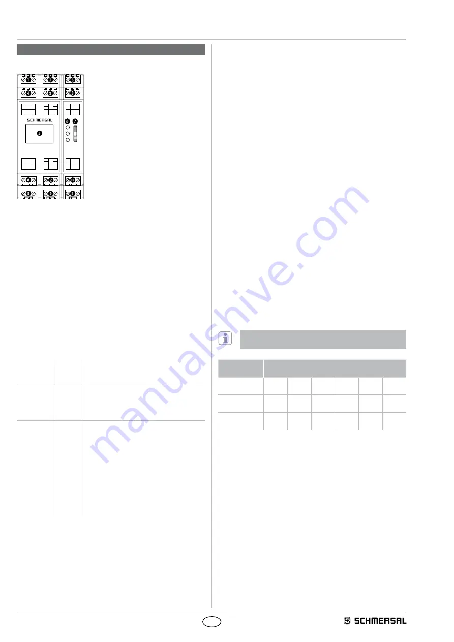
5.1  Connection / operating elements

PROTECT

Run

Q0N

I12

Y2 I13

I14

Y3

T1 T2

A1 A2 FE

I0

Y0 I2

I4

Y1

I1 I3 I5

T0

Q2 Q1

Q0 Q3 Q1N

QR0 QR2

QR1

AI0 AGND AI1

I15 I16 I17

I6 I8 I10

I7 I9 I11

UB

ERR

1

2

2

3

3

3

3

4

5

6

7

8

10

9

8

1  Cycle outputs T0...T2

2   Safe inputs /  

optional signalling outputs

3  Safe inputs

4  Supply voltage

5  Graphic colour display

6  Status LEDs

7  Rocker switch

8  Safe semi-conductor outputs

9  Safe relay outputs

10  Safe analog inputs

Operating the rocker switch

Up/down:  Navigation through the menu and the input masks.

Press:  

Acceptance of the entry or confirmation of an action.

LED indications

U

B


lights up 

operating voltage applied

Run 

lights up 

operating mode


blinking 

 Configuration mode or module has the factory 

defaults (see initial parameterization)

ERR 

illuminates  A fault is present (safe condition)


blinking 

 There is a caution or warning  

(Operation with possible limitations)

Fault / Warnings / Messages appear on the display in plain text.

Menu structure

The complete structure may be derived from Chapter 7.

5.2  Description of the terminals

Voltage

A1
A2
FE

+24 VDC
0 VDC
functional earth connection

Inputs

I0...I17
AI0
AI1
AGND

Safe digital inputs
Safe analogue input
Safe analogue input
Analogue ground

Outputs

Q0, Q0N
Q1, Q1N

Q2
Q3
QR0
QR1
QR2
Y0...Y3
T0...T2

Safe semi-conductor output p-/n-switching
Safe semiconductor output p-/n-switching 
(only available OEM-products)
Safe semi-conductor output p-switching
Supply of safe relay output
Safe relay outputs
Safe relay outputs
Operational outputs (signalling output)
Clock outputs for the supply of safe digital 
inputs for short-circuit recognition

5.3  Start level

Alternatively:  

 auto-start or manual start (falling edge)

Optional:  

feedback circuit (EDM), start-up testing

Start-up test

After switching on the supply voltage again the protective device must 

first be opened and closed again before the enable can be activated 

with the start/RESET button.

5.4  Sensor level

18 safe digital inputs

Selectable:  

 1-channel of 2-channel, equivalent,  

antivalent or deactivated.

Optional condition:    Short circuit recognition,  

discrepancy monitoring

2 safe analogue inputs

2 analogue safe 1-channel inputs each with 4 adjustable limit values 

or 1 analogue safe 2-channel input with 4 adjustable limit values and 

adjustable monitoring of the percentage (of maximum value = 4095) 

channel deviation.

Discrepancy monitoring

After a request for a 2-channel protection device that is carried out by 

only one of the input channels, both input channels must be opened 

and closed again before the release with the START / RESET button 

can be activated.

Cross-wire detection

Measure for detecting short circuits between the input channels for 

2-channel operation. The cross-circuit detection is achieved here by 

the use of clock outputs T0 ... T2 using floating safety sensors. The 

assignment of the clock outputs to the inputs is fixed. The setting takes 

place in the inputs menu.

To reach cat. 4 / PL e / SIL CL 3, cross-circuit detection  

must be enabled in floating safety sensors.

Cycle outputs

Digital inputs I00 … I17  

(optional signalling outputs Y0 … Y3)

T0 closed

I00  

(Y0)

I03

I06

I09

I12  

(Y2)

I15

T1 closed

I01

I04  

(Y1)

I07

I10

I13

I16

T2 closed

I02

I05

I08

I11

I14  

(Y3)

I17

Analogue limit values

The limit values are set with a number of between 0 to 4095.

The following conversion applies:

Limit value = Voltage [V] x 337

Summary of Contents for PROTECT SELECT

Page 1: ...neral information for electrical connection 4 4 2 Power supply 4 4 3 Start level 4 4 4 Sensor level 4 4 5 Actuator level 5 5 Operating principle and settings 5 1 Connection operating elements 6 5 2 De...

Page 2: ...se If used incorrectly or not for the intended purpose or in the case of tampering danger to persons or damage to machine and system parts from using the safety module cannot be ruled out 1 7 Exclusio...

Page 3: ...t change Sinusoidal max 2 8 Hz max 50 mA s Input resistance 10 k Safe analogue inputs Category PL SIL CL Single channel If a cable break dominates Cat 3 PL d SIL CL 2 Dual channel Cat 4 PL e SIL CL 3...

Page 4: ...d pins Electrical power cables must be routed separately from communication lines 3 2 Disassembly Unlock the bottom of the enclosure by means of a slotted screwdriver push up and hang out slightly til...

Page 5: ...onductor outputs Q2 Q3 with 24 VDC 2 x safe relay outputs QR1 QR2 with common supply QR0 up to 250 VAC or 24 VDC 4 x operational optional message outputs Y0 Y 3 with 24 VDC Relay outputs 250 V 24V GND...

Page 6: ...y outputs Operational outputs signalling output Clock outputs for the supply of safe digital inputs for short circuit recognition 5 3 Start level Alternatively auto start or manual start falling edge...

Page 7: ...processor MSP which is parameter assigned by a three digit hexadecimal number The 1 position describes the sensor the 2 position the additional function and the 3 position the contact properties The e...

Page 8: ...ing locked guard interlocks Power to lock For solenoid locked guard interlocks The interlock type always applies to all connected guard interlocks Analog inputs Dual Sensor 2 channel analysis of AI0 a...

Page 9: ...the list After entry a plain text display of the selected settings appears ENTER moves back to the code list display If you navigate up with the last MSP code the next menu appears MSP 01 1 A 5 MSP 0...

Page 10: ...leshooting Description of possible error cause and rectification measures Restart Trigger of a new start once the error has been eliminated Configuration Enter PIN Entry of the PIN codes so as be able...

Page 11: ...essary Sensors and emergency stop command devices can be reset in any order Sensor level Safe analogue inputs Implemented in the following application programs for both analogue secure inputs are the...

Page 12: ...ital inputs I00 I01 Operating mode selector switch automatic I00 HIGH I01 LOW manual I00 LOW I01 HIGH I02 I03 Enabling switches MSP 6 Default value 0 0 0 I04 I05 1 sensor MSP 2 Default value 0 0 0 I06...

Page 13: ...ayed Signalling output Y3 error message status indication Manual mode Flashing with 2Hz Warning Flashing with 1Hz Error messages Lights up Safe semi conductor outputs Q0 Q0N Stop 0 or Stop 1 All semic...

Page 14: ...lay outputs QR1 QR2 Stop 0 or Stop 1 All relay outputs are linked to a safe timer Timer Off Delay Stop 0 Timer 0 seconds Default value Stop 1 Timer should be actively adjusted to 0 seconds Application...

Page 15: ...4 sensor MSP 5 Default value 0 0 0 I10 I11 5 sensor MSP 6 Default value 0 0 0 I12 I13 Feedback circuit I14 I15 START RESET or latch interlock for I16 I17 I16 I17 Emergency stop command device MSP 1 De...

Page 16: ...00 Monitoring time for MSP 5 T11 10 00 Monitoring time for MSP 6 T12 10 00 Stable time for MSP 1 E Stop T13 0 10 Stable time for MSP 2 T14 0 10 Stable time for MSP 3 T15 0 10 Stable time for MSP 4 T1...

Page 17: ...conductor outputs are linked to a safe timer Timer Off Delay Stop 0 Timer 0 seconds Default value Stop 1 Timer should be actively adjusted to 0 seconds Safe relay outputs QR1 QR2 Stop 0 or Stop 1 All...

Page 18: ...The muting monitoring time continues The muting lamp Y0 remains on The muting outputs remain set e The workpiece releases the light barrier AOPD The muting monitoring time continues The muting lamp Y0...

Page 19: ...art the safety monitoring the high signal is absent at the corresponding input which means the feedback loop of the integrated actuator is not closed Timeout Disturbed safety switch The time lag betwe...

Page 20: ...56 12103 Berlin ID n 0035 Person authorized for the compilation of the technical documentation Oliver Wacker M ddinghofe 30 42279 Wuppertal K A Schmersal GmbH Co KG M ddinghofe 30 D 42279 Wuppertal P...

Reviews: