


13
PROTECT SELECT
PROTECT SELECT OEM
Operating instructions
Multifunctional safety controller
EN
In addition, the inputs can be changed as individual sensors I16 and I17
together with the default setting "Emergency Stop command device".
This sensor evaluation for the inputs I16 and I17 have a higher priority
and will not be bridged by the "operation mode selector
enabling device".
Via the inputs I00 and I01 an operating mode selector switch is evaluated.
The selection of the operating mode selector switch is as follows:
- Automatic mode: I00 = HIGH and I01 = LOW
- Manual mode:
I00 = LOW and I01 = HIGH
When the operating mode selector switch is set to "manual mode",
the sensors can be bridged via the inputs I04 to I11 in their safety
monitoring via an enabling switch to the inputs I02 and I03.
The condition START / RESET via the input I15 is permanently
assigned to the inputs I16 + I17 and I04 to I11
The connected sensors I04 to I11 switch off the outputs Q0/Q0N,
Q2 and Q3, QR1 and QR2.
Digital inputs I12, I13, I15
• Input I12 (unlock interlock: " Open door request"):
Request to unlock the guard interlock so that the safety area can be
accessed.
• Input I13 (feedback circuit):
Feedback circuit from the actuators (e.g. guards, drive regulator,
inverter, valve terminal etc.) is switched as an additional condition to
the function macro.
• Input I15 (RESET for the Emergency-Stop command device and for
the sensors I04 to I11):
- Restart condition after the Emergency-Stop control device has been
actuated.
- Restart condition of the safety sensors, connected to the inputs I02
to I11.
- Request for locking the guard interlock after leaving the safety area
and the safety equipment has been closed.
Signalling outputs Y3
• Signaling output Y3:
for the information transfer that an error has occurred with an error
message or warning with a warning message on the display. This
message output can also be used to control a corresponding fault or
warning message lamp.
Also via the signaling output Y3 the message "Manual operation is
active" is transferred and displayed.
Signalling output Y3, error message / status indication:
Manual mode:
Flashing with 2Hz
Warning:
Flashing with 1Hz
Error messages: Lights up
Safe semi-conductor outputs Q0/Q0N
• Stop 0 or Stop 1:
All semiconductor outputs are linked to a safe timer (Timer Off Delay).
Stop 0: Timer = 0 seconds (Default value)
Stop 1: Timer should be actively adjusted to 0 seconds
• Additional function selection for a possible connected interlock:
Working current Yes / No
Safe semi-conductor outputs Q2, Q3
• Stop 0 or Stop 1:
All semiconductor outputs are linked to a safe timer (Timer Off Delay).
Stop 0: Timer = 0 seconds (Default value)
Stop 1: Timer should be actively adjusted to 0 seconds
Safe relay outputs QR1, QR2
• Stop 0 or Stop 1:
All relay outputs are linked to a safe timer (Timer Off Delay).
Stop 0: Timer = 0 seconds (Default value)
Stop 1: Timer should be actively adjusted to 0 seconds
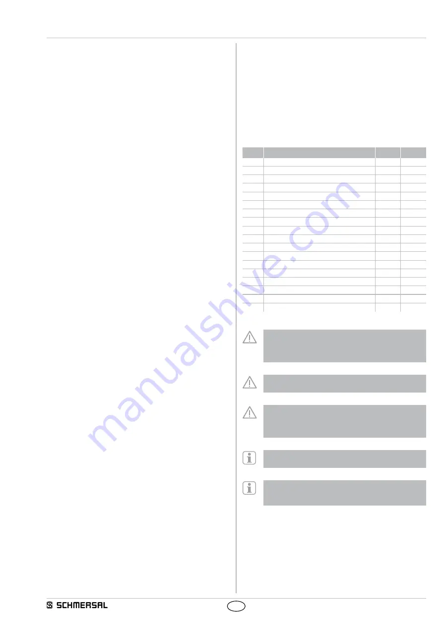
Timers used
Name Function
Timer
Time [s]
TOF 0 Shut down delay for Q0/Q0N
T00
0.00
TOF 2 Shut down delay for Q2
T02
0.00
TOF 3 Shut down delay for Q3
T03
0.00
TOF 4 Shut down delay for QR1
T04
0.00
TOF 5 Shut down delay for QR2
T05
0.00
Monitoring time for MSP 1 (E-Stop)
T07
10.00
Monitoring time for MSP 2
T08
10.00
Monitoring time for MSP 3
T09
10.00
Monitoring time for MSP 4
T10
10.00
Monitoring time for MSP 5
T11
10.00
Monitoring time for MSP 6
T12
10.00
Stable time for MSP 1 (E-Stop)
T13
0.10
Stable time for MSP 2
T14
0.10
Stable time for MSP 3
T15
0.10
Stable time for MSP 4
T16
0.10
Stable time for MSP 5
T17
0.10
Stable time for MSP 6
T18
0.10
Stable time for MSP 7 (analogue E-Stop) T19
1.00
Employment of this user program requires observation of
chapters 9.2.3, 9.2.4, 9.2.6.3 and 10.9 of EN 60204-1:2006.
Special requirements from these chapters must be realised
by a higher ranking control.
When changing the operating mode, the outputs initiate a
stop 0 or stop 1.
On the inputs I04 to I11 (first to fourth sensor) there should
be no Emergency-Stop command device connected.
Emergency-Stop command devices are only allowed to be
connected to the inputs I16/I17.
After Power ON and after an operational mode change a
START/RESET is necessary.
The enable device is to be configured as a contact safety
switch (floating) with auto start.
Example: MSP code = 0 9 2 or 0 B 2