Schmalz VCMC-R QUICK Operating Instructions Manual Download Page 14

 WARNING

Flying workpiece due to insufficient clamping force during processing resulting from incor-
rect setting of the clamping height.

Risk of injury due to flying workpiece

4

Adjust the clamping height such that the VCMC uses its maximum clamping force. While doing
so, ensure that the lifting force of the VCMC is less than or equal to 6 mm.

4

Personal protective clothing must be worn.

ü

The locking disc must be entirely closed.

ü

The workpiece is set.

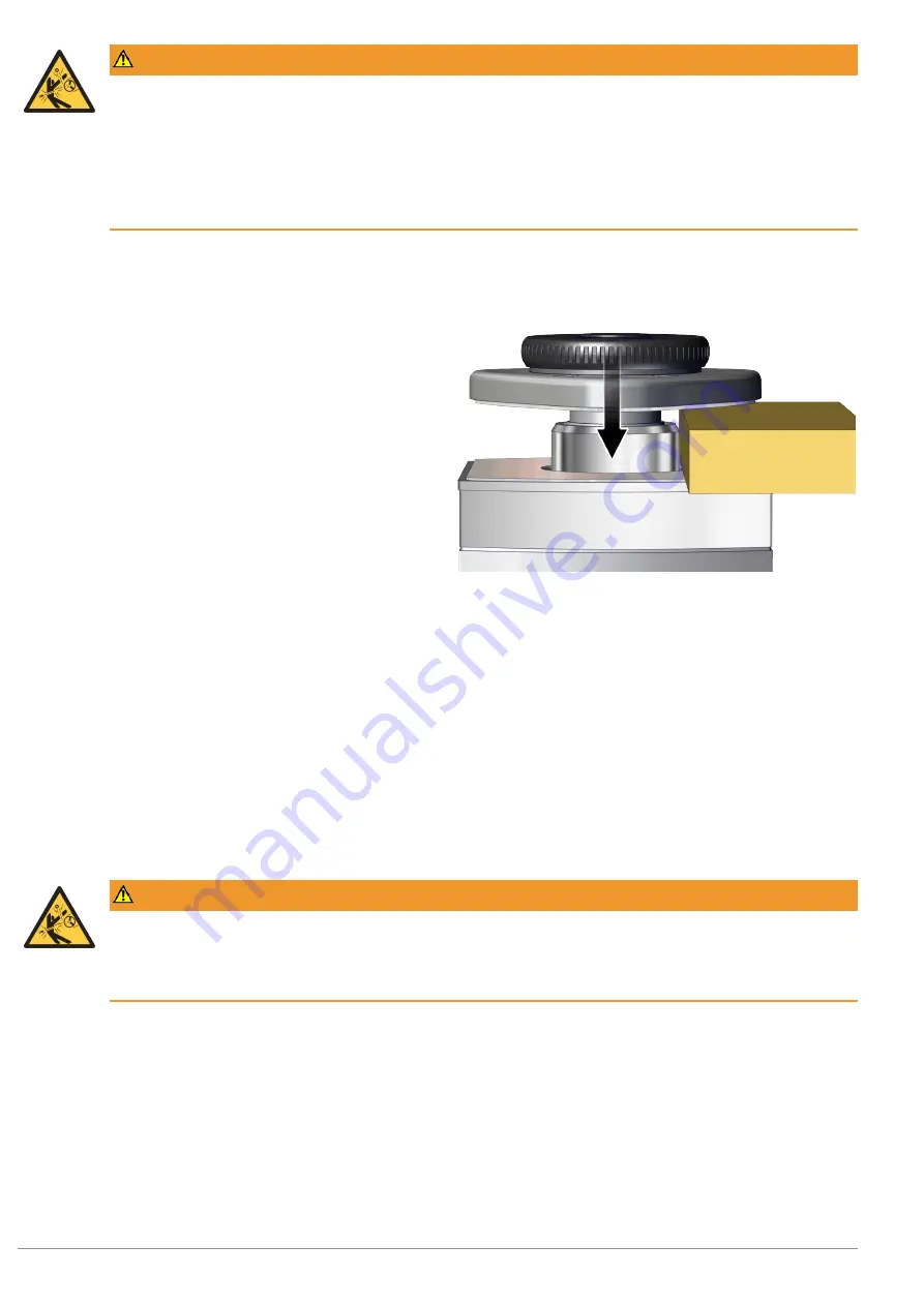
1. Evacuate the appropriate vacuum circuit on the

grid table via the higher-level machine.

ð

The VCMC is clamped to the grid table and the
workpiece is clamped by lowering the clamping
disc (

 6 mm).

2. Carry out both a visual and manual check to make

sure that the workpiece is securely clamped by
pulling on the workpiece.

ð

If the workpiece can be moved, then it is not sufficiently tightly clamped. Check the clamping height and ad-
just it if necessary.

ð

If the clamping is sufficient, then machining of the workpiece may commence.

7.2  Machining Limitations

 WARNING

The workpiece comes loose during machining and is flung away by the machine.

Risk of injury from flying parts.

4

Ascertain the maximum machining parameters and observe them.

The clamping force is limited, meaning that it can withstand machining forces only up to a certain point. Accord-
ingly, the operator of the mechanical clamp is obligated to establish for themselves (by experiment, slowly and
carefully increasing the machining forces) the optimal settings and number of mechanical clamps necessary to en-
sure that the workpiece does not slip or even come loose during the machining process.

Schmalz assumes no liability for damages resulting from slippage or release of workpieces due to faulty adjustment
of machining parameters.

14 / 15

EN-US · 30.30.01.03049 · 00 · 10/21

Summary of Contents for VCMC-R QUICK

Page 1: ...Schmalz GmbH 10 21 This document is protected by copyright J Schmalz GmbH retains the rights established thereby Reproduction of the contents in full or in part is only permitted within the limits of...

Page 2: ...ption of Mechanical Clamp VCMC 5 3 1 1 Use 5 3 1 2 The Adjustment Mechanism 5 3 1 3 Clamping the Workpiece 5 3 2 Design of Mechanical Clamp VCMC 6 3 3 Near Field Communication NFC 6 4 Technical Data 7...

Page 3: ...malfunctions that result from failure to heed these instructions If you still have questions after reading the technical documentation contact Schmalz Service at www schmalz com services 1 3 Type Plat...

Page 4: ...e the following During installation the clearance between the workpiece surface and the clamping disc must be no more than 6 mm Caution crushing hazard Do not allow anyone to reach between the workpie...

Page 5: ...ition as delivered 2 Use only original spare parts from Schmalz 3 The product must be operated only in perfect condition 3 Product Description 3 1 Description of Mechanical Clamp VCMC 3 1 1 Use The VC...

Page 6: ...3 3 Near Field Communication NFC NFC Near Field Communication refers to a standard for wireless data transfer between different devices over short distances An NFC chip is integrated in the locking di...

Page 7: ...sed The following parameters can be queried via NFC Product group Type Part number Index Serial number Year of manufacture encoded 4 Technical Data 4 1 General parameters Stroke length Z all 9 mm Dete...

Page 8: ...and J Schmalz GmbH 6 Installation 6 1 Installation Instructions The VCMC R is designed for grid tables with grids measuring 30x30 40x40 and 50x50 and slot widths between 5 and 7 mm Mounting and remova...

Page 9: ...lot widths from 5 mm Size 6 0 for slot widths from 6 mm Size 6 5 for slot widths from 6 5 mm Position R30 Position R40 Position R50 Grid dependent positions for positioning inserts and sealing frame A...

Page 10: ...sure that there is an open vacuum feedthrough in the grid table within the sealing frame 5 Check the position The positioning inserts lock positively into the slots The VCMC R is in full contact with...

Page 11: ...ism Turn the locking disc counterclockwise until the quick adjustment mechanism is completely opened 2 Releasing the catch of the quick adjustment mech anism Clasp the clamping disc with both hands an...

Page 12: ...ping Range CAUTION When the clamping disc is lowered body parts may be present in the clamping range Crushing of body parts 4 Ensure that the clamping height is set so that the distance between the cl...

Page 13: ...unterclockwise and remove it from the clamping disc 1 4 Screw the clamping disc clockwise onto the clamp 5 Open the quick adjustment mechanism see step 1 above 6 For the next steps see section Setting...

Page 14: ...n be moved then it is not sufficiently tightly clamped Check the clamping height and ad just it if necessary If the clamping is sufficient then machining of the workpiece may commence 7 2 Machining Li...

Page 15: ...3 NBR 55 Sealing frame for R50 Wearing part 10 Disposing of the Product CAUTION Flying parts resulting from opening the mechanical clamp and releasing the spring Serious injury 4 Open the mechanical c...

Reviews: