background image

4  •  Schlage  •  CT5000 user guide

Getting started

Before installing the CT5000, read all documentation for all products in the 

installation.

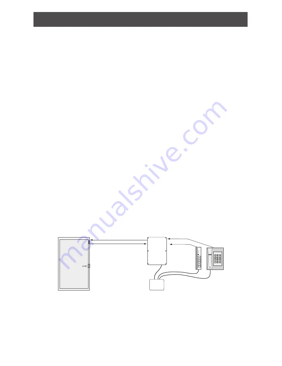
1.  Determine the location of each component in the access control system. 

The CT5000 

must be installed indoors.

2.  To operate at optimum efficiency, cable runs should be kept as short as possible.

3.  Consult the National Electrical Code (NEC) and local electrical codes for information 

regarding wire run lengths and minimum required wire gauge.

4.  Install the UL listed reader(s) as specified in the control unit installation instructions.


L

The CT5000 may not control or configure the reader’s beeper or LED settings. 

Consult the reader’s user guide for more information on configuring the reader’s 

beeper or LED patterns.

5.  Install the UL listed electrified locking hardware. See the manufacturer’s installation 

guide that came with the hardware. For installation instructions and information for 

Schlage electrified locks, visit the Schlage website at www.allegion.com/us (see 

Support>Schlage Electronics>Electronic Locks Technical Library).

6.  Install the CT5000. 

A U.S. single gang electrical box (not included) is required for 

the remote USB connection

. See 

Remote USB connection

 on page 13.

7.  Install a UL294 or ULCS318/ULCS319 listed power supply (example: Schlage PS900 

Series) for the CT5000 and the readers. The power supply must be compatible with all 

components and must have the capacity to power the CT5000 

and

 the readers. (The 

CT5000 requires a power supply capable of sourcing at least 500 mA @ 12 or 24 VDC.)


L

If preferred, separate UL294 or ULCS318/ULCS319 listed power sources for the 

CT5000 and the readers is an acceptable alternative.

8.  Make sure power is properly connected to all components in the system.

9.  After power is applied, remove the mylar strip from the coin cell battery.

10. Make all wiring connections.

11. Configure and program the CT5000. See 

CT5000 manual programming

 on page 16.

12. Test the operation of the CT5000 with the electrified locking hardware. See 

Test

 on 

page 21.

Save this user guide for future reference.

CT5000

Credentials

Readers

Door hardware

connections

not shown.

0   1
2   3

6   7

4   5

*   #

8   9

Power

Supply

UL listed exit

device or lock

Typical installation

Compatible credential reader output formats:

•  Wiegand and Clock & Data formats are compatible with the CT5000.

•  Keypad formats compatible with the CT5000 are: ASCII with leading parity, 4-bit, 

8-bit and 26-bit Wiegand

.

 (Note: Manual programming and card plus pin are not 

supported in 26 -bit Wiegand.)

Summary of Contents for CT5000

Page 1: ...DPS RTX GND DEBUG TAMPER STATUS RELAY RX TX USB 12V 5V LID 3 3V RX TX GND OPEN A 1 1 1 1 1 1 1 1 23394075_C SCHLAGE LINK RESET TAMPER GND ICLK IDAT RB8 RB7 GND VDD MCLR USB AA BATT LINE ALR_NC ALR_C ALR_NO AUX AUX AUX STR STR STR RB TB TA RA RS485 12 24VDC THIS MOUNT LED2 BATTERY_HOLDER1 R112 C61 U4 REL1 J3 J7 REL2 REL3 U5 TP25 TP24 TP23 TP22 TP21 J6 LED1 LED4 LED7 LED5 LED6 LED3 J18 J17 J13 LED8 ...

Page 2: ... types 16 Programming legend 17 Manual programming commands 17 Manual programming error codes 20 Using the CT5000 controller 20 Reader LED reference 20 CT5000 coin cell battery 21 Test 21 Test the CT5000 with power applied 21 Schlage button test 21 CT5000 in construction mode 21 CT5000 and door file test 21 Troubleshooting 22 CT5000 LED reference 23 FCC IC statements 24 This product is compliant o...

Page 3: ...and or sold by Allegion is not rated for or intended for use in life safety installations UL listed panic hardware must be used to allow emergency exit from the protected area Before installing the CT5000 controller read all documentation for all products in the installation C B 1 1 1 GND GND IF RADIO BOARD PRESENT NC BATT COIN CELL NOT NEEDED NC C NO C NO PRIMARY SIDE BEEPER BEEPER ALARM STRIKE A...

Page 4: ...or the remote USB connection See Remote USB connection on page 13 7 Install a UL294 or ULCS318 ULCS319 listed power supply example Schlage PS900 Series for the CT5000 and the readers The power supply must be compatible with all components and must have the capacity to power the CT5000 and the readers The CT5000 requires a power supply capable of sourcing at least 500 mA 12 or 24 VDC L L If preferr...

Page 5: ...ith two 2 UL listed credential readers and supports three 3 output relays strike auxiliary and alarm and four 4 optional inputs reader 1 tamper reader 2 tamper request to exit and door position switch Request to enter is not supported on the CT5000 Use cable entry exit connectors that comply with local electrical codes i e conduit etc Drill hole s in the CT5000 enclosure to accommodate the size an...

Page 6: ...lden 8760 18 Credential reader tamper Belden 8760 18 Credential reader 1 Alpha 1296C 22 6 conductor shielded Alpha 1298C 22 8 conductor shielded Credential reader 2 Alpha 1296C 22 6 conductor shielded Alpha 1298C 22 8 conductor shielded Typical application See Cable wire table 2 for load power wire runs Cable wire table 2 Total length of one wire run Load current 12 VDC Load current 24 VDC 1 4 A 1...

Page 7: ...nge the state of the strike relay Switch closed GND Request to exit GND J13 5 Ground Electrical ground common for the CT5000 DPS J13 6 Door position switch By default the CT5000 assumes there is no DPS connected To install DPS a Handheld Device HHD with Schlage Utility Software sold separately is necessary to change the configuration of the system to indicate that a DPS is installed When DPS is in...

Page 8: ...is capable of switching up to a 2 amp resistive load at 24 VDC or 0 5 amp at 120 VAC Note The CT5000 alarm operates only when a DPS is installed and the CT5000 is properly configured with the HHD By default the CT5000 assumes there is no DPS connected To install DPS a Handheld Device HHD with Schlage Utility Software sold separately is necessary to change the configuration of the system to indicat...

Page 9: ... the reader s beeper or LEDs Please consult the reader s manufacturer for instruction on reader configuration Make sure your reader is configured with the LEDs and beeper OFF for best compatibility Reader 1 terminal Reader 2 terminal Description CLK D1 J17 1 J18 1 Credential reader inputs Each input line is pulled to GND through a 12V transient suppressor and a 2 mega ohm resistor Wiegand or magne...

Page 10: ...0 19 2 1 ICLK IDAT RB8 RB7 GND VDD MCLR USB AA BATT LINE ALR_NC ALR_C ALR_NO AUX AUX AUX STR STR STR RB TB TA RS485 12 24VDC THIS MOUNT LED2 BATTERY_HOLDER1 R112 C61 U4 REL1 J3 J7 REL2 REL3 U5 TP25 TP24 TP23 TP22 TP21 J6 LED1 LED4 LED7 LED5 LED6 LED3 J18 J17 J13 LED8 LED9 C32 J9 J12 J11 J10 J8 S3 S2 S1 J5 J2 J1 Fail Safe Locking Hardware Max 6 Amps 24 VDC SWITCH INPUT UL or ULC Listed 12 or 24 VDC...

Page 11: ... 19 2 1 ICLK IDAT RB8 RB7 GND VDD MCLR USB AA BATT LINE ALR_NC ALR_C ALR_NO AUX AUX AUX STR STR RB TB TA RS485 12 24VDC THIS MOUNT LED2 BATTERY_HOLDER1 R112 C61 U4 REL1 J3 J7 REL2 REL3 U5 TP25 TP24 TP23 TP22 TP21 J6 LED1 LED4 LED7 LED5 LED6 LED3 J18 J17 J13 LED8 LED9 C32 J9 J12 J11 J10 J8 S3 S2 S1 J5 J2 J1 Fail Secure Locking Hardware Max 6 Amps 24 VDC SWITCH INPUT UL or ULC Listed 12 or 24 VDC Po...

Page 12: ...modes The CT5000 strike relay can be configured to fail safe fail unlocked or fail secure fail locked using SUS on the HHD The default state of the strike relay is fail secure or normally closed secure on the HHD Auxiliary and alarm relays can also be configured Please use the chart below as a recommended wiring guideline with various types of electronic locking hardware To maximize security a val...

Page 13: ...cable to the USB wall plate using the included hardware 4 Route the 15 foot USB cable through the single gang electrical box and connect it to the panel mount USB cable 5 Attach the USB wall plate to the single gang electrical box using the included hardware 6 Connect the USB cable to the CT5000 The CT5000 can now be configured and programmed with the HHD through the USB wall plate L L The lid mus...

Page 14: ...D blinks green and the HHD display indicates new lock no door data available or the name of the door file The SUS is now ready to view the CT5000 settings 5 To Edit Settings or Update Firmware on the CT5000 the SUS software and the CT5000 must be coupled To couple the CT5000 and the HHD On the CT5000 press and hold the SCHLAGE button while pressing the LINK button three 3 times within 5 seconds Th...

Page 15: ...ader s LED will blink green five 5 times Cancel construction access mode Do one of the following Program the lock with the HHD See the SUS User Guide for more information Reset the lock to factory settings See Reset to factory defaults on page 15 for information When construction mode is cancelled the master construction credential and all other credentials added using the master construction cred...

Page 16: ...e state PIN 3 6 digits OR card Toggle PIN PIN 3 6 digits AND card Freeze Freezes the lock in the current state CT5000 controller remains frozen until Freeze credential is presented again PIN 3 6 digits OR card Freeze PIN PIN 3 6 digits AND card Pass Through Unlocks a lock momentarily regardless of state Overrides a CT5000 controller in Freeze state PIN 3 6 digits OR card Pass through PIN PIN 3 6 d...

Page 17: ... blinks of the green DEBUG LED and the reader s green LED will blink L L The reader s red LED will blink to indicate an incorrect entry To interpret blink patterns refer to page 20 Function Press Present Confirmation1 Change Programming Code Programming Code OR Programming Card Wait for green LED to stop blinking between each step New Programming Code New Programming Code Change Programming Card P...

Page 18: ...ze PIN Credential Programming Code OR Programming Card Wait for green LED to stop blinking between each step New PIN New Card add another credential OR to finish Add Pass Through Credential Programming Code OR Programming Card Wait for green LED to stop blinking between each step New PIN for PIN only OR New Card add another credential OR to finish Add Pass Through PIN Credential Programming Code O...

Page 19: ...rogramming Code OR Programming Card Wait for green LED to stop blinking between each step New CODE for CODE only OR New Card add another credential OR to finish Main Aux Toggle Programming Code OR Programming Card Wait for green LED to stop blinking between each step New CODE for CODE only OR New Card add another credential OR to finish Change Relock Delay Programming Code OR Programming Card Wait...

Page 20: ...lows Credential type Action Credential Present credential to reader Green blink and access granted PIN Credential Present credential to reader Press PIN 1 Green blink and access granted 1 The default PIN length is six digits The key must be used as an ENTER key for PINs with fewer than six digits PIN length can be manually configured refer to Change PIN Length on page 19 Reader LED reference The C...

Page 21: ...s LED and beeper performance is irregular or unexpected refer to the instructions that came with the reader Schlage button test L L Performing the Schlage button test will not result in the loss of any CT5000 settings or programming changes 1 While holding the SCHLAGE button press and release the RESET button 2 All relays on board LEDs reader LEDs and reader beeper will be active while the SCHLAGE...

Page 22: ...r s user guide for more information on configuring the reader s beeper or LED patterns HHD is not communicating with the CT5000 No USB LED HHD display reads No Device Connected Make sure the USB connector is properly connected The USB LED will blink green Set the HHD connection type to USB See Handheld Device HHD on page 14 Unable to configure settings with HHD HHD display reads Your HHD is not au...

Page 23: ...d hold SCHLAGE button press LINK button 3 times within 5 secs Coupling window is enabled for 30 secs Construction Mode Programming To program a master construction credential Press and hold SCHLAGE button then present valid credential to the reader within 5 secs If the credential is not presented within 5 seconds time out will occur Note CT5000 must be in factory default state to program the maste...

Page 24: ...onable protection against harmful interference in a residential installation This equipment generates uses and can radiate radio frequency energy and if not installed and used in accordance with the instructions may cause harmful interference to radio communications However there is no guarantee that interference will not occur in a particular installation If this equipment does cause harmful inte...

Reviews: